金属焊接(超声)
超声金属焊接是通过施加剪切(摩擦搓动)模式的超声振动将两个金属零件连接在一起的工艺。超声振动会挤开两个零件界面处的表面氧化物和污染物,从而实现紧密的金属对金属接触,进而形成焊缝。焊接温度相对较低,不涉及熔化。
超声金属焊接最适合较软的金属(铝、铜、黄铜等),不过稍硬的材料(如钛)也可以焊接。硬度相近的异种材料也可以焊接(如铜与铝)。超声金属焊接可用于电阻焊难以胜任的高导电率材料。
点焊
图 1(Al‑Sarraf[1],第 9 页)展示了两种基本的金属焊接构型 — Wedge-reed(楔-簧片)系统和横向驱动系统。
|
|
|
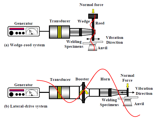
Wedge-reed 系统
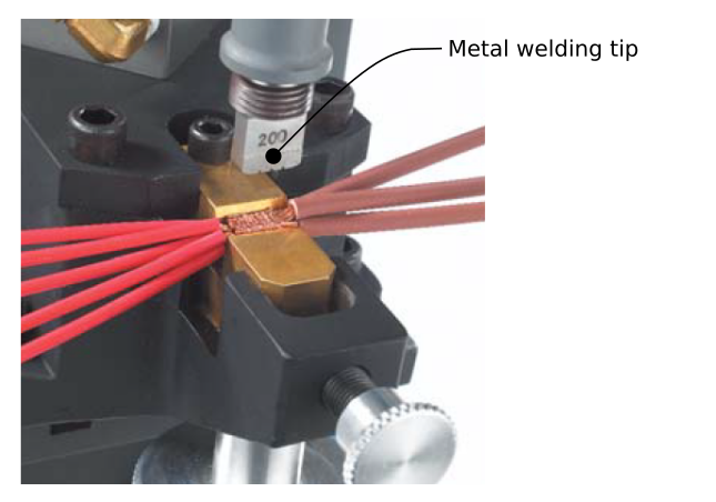
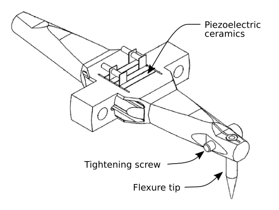
Wedge-reed 系统由 Aeroprojects 开发(Jones[4] 专利 2,946,119,1960 年),目前由 Sonobond Ultrasonics(Aeroprojects 的继承者)使用。该系统的驱动部分由一个水平安装的换能器和一个楔形变幅杆组成;变幅杆钎焊在一根竖直安装的谐振簧片上。变幅杆激励簧片作弯曲振动,进而驱动安装在簧片自由端的可更换锥配合焊接端头(图 2)。所需的焊接力施加在簧片另一端的质量块上。
根据应用需要,该系统可以设计成带两根共线相对布置的簧片,其中一根充当砧座。二者反相工作,从而有效地将焊接振幅和可用功率加倍。
该系统以相对较高的力和较低的振幅工作。
|
|
|
横向驱动系统
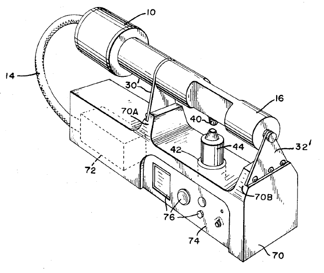
在开发 Wedge-reed 系统之后,Aeroprojects 随后又开发了横向驱动系统(Jones[5] 专利 3,209,447,1965 年)。Branson Ultrasonics 后来开发了一种在波腹处采用弯曲谐振支撑构件的横向驱动系统(Shoh[1] 专利 3,752,380,1973 年,图 3)。该系统的进一步发展和变型(尤其是安装方式方面)至今仍在使用。
|
|
|
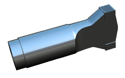
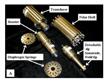
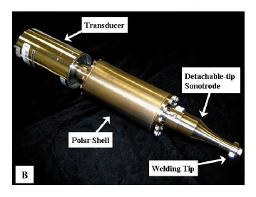
变幅杆可以是实心的(通常为淬硬钢,图 4),也可以带可更换的多瓣焊接端头(Holze[1] 专利 3,813,006;见图 5 和附录 A;另见安装设置)。超声叠堆通常安装在某种圆柱形壳体内(例如图 6 的极轴安装座),使叠堆可以绕其(极)轴旋转,从而使多瓣端头相对于工件正确定向。由于其轴对称性,这种布置也很适合缝焊。(注意 — 图 6a 中增幅杆的方向画错了,螺柱应朝向换能器。)
双驱动
|
|
|
|
|
|
|
||||||||||
|
系统比较
焊接质量
焊接质量由许多因素决定(其中重要的是电源的过程控制,但这超出本讨论范围)。两种系统略有差异的一个方面是端头运动的施加方式。在两种系统中,端头都对工件施加剪切运动。然而,Wedge-reed 端头还因簧片的弯曲而带有一些摇摆运动。目前尚不清楚这会在多大程度上影响(可能改善)焊接质量。
振幅塌陷?
夹紧力
根据 Sonobond 的产品资料,"Wedge-reed 系统的特点是振动振幅低、振动力高,适合焊接金属。"相比之下,"横向驱动系统的特点是振动振幅高、振动力低,适合焊接塑料。""由于(横向系统的)悬臂结构,夹紧力施加在距焊缝一定距离处,在耦合件上产生弯矩,从而限制了静态力。这使得横向驱动系统无法为镀锡或氧化的导线和端子焊出合格的焊缝。"
注意 — 横向驱动系统的特征是变幅杆相对于被焊零件的取向,而不是变幅杆的支撑方式。
横向驱动支撑系统
Shoh 专利 3,752,380(图 3)展示了一种横向驱动系统,其中带焊接端头(40)的变幅杆(16)被支撑在两根竖直(弯曲谐振)构件(30 和 32)之间。在这种布置中,端头上没有弯矩。因此,允许的夹紧力仅受支撑构件强度的限制。(另请参阅 — Jones[5] 专利 3,209,447,该专利讨论了同一问题;Roberts[3] 专利 6,078,125,此处有讨论。)
在变幅杆悬臂安装的横向驱动系统中(图 1,下图;图 5),夹紧力会使焊接端头产生竖直方向甚至水平方向的挠曲。由于悬臂结构,竖直挠曲会使端头的焊接面相对于砧座略微倾斜(如同张开一把剪刀)。挠曲量及由此产生的错位程度取决于叠堆和支撑结构的刚度,也取决于夹紧力。
对于许多应用(例如管子封口),这种挠曲不会造成问题。此外,如果端头带有圆角,由于端头基本上是自定向的,这可能也不是问题。然而,某些应用(如导线搭接和导线端接)可能需要更严格的对中。例如,Patrikios[1] 专利 8,113,258 指出"焊接端头的位置必须保持在 3 微米(0.001 英寸)以内"(第 1 栏,第 42 行)。(注意,3 微米(3*10-6 m)换算为 0.0001 英寸而非 0.001 英寸,因此该规定要求并不明确。不过,无论哪个要求都相当严格。)
当变幅杆悬臂安装时,有一些方法可以减小变幅杆的竖直挠曲。
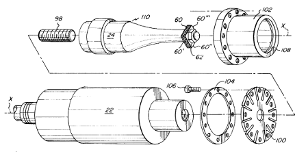
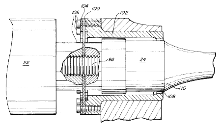
- 使用非常刚性的支撑。例如,Patrinkios[1] 专利 5,772,100(图 7)展示了一种设计,其套环(102)通过表面 108 抵在变幅杆的波节上。该套环保持固定,使表面 108 限制变幅杆的竖直挠曲。套环通过位于变幅杆波腹处的膜片(100)与变幅杆在超声上隔离,类似于 Shoh[3] 专利 3,955,740 的极轴安装膜片。(有趣的是,Partikios 专利并未将 Shoh 专利引为现有技术。)与极轴安装座一样,该设计不限制变幅杆的横向(轴向)运动。与极轴安装座相比,该设计还有三个额外的优点 —
- 在极轴安装座中,增幅杆必须调谐到能装入壳体长度之内,或者反过来,壳体必须加垫片以适配现有增幅杆的长度。由于 Patrikios 设计不使用后部膜片,其增幅杆长度不受限制。因此,任何现成的商用增幅杆都可以使用。
- 在极轴安装座中,增幅杆直径受壳体内径限制。由于 Patrikios 设计没有包围增幅杆的壳体,其直径不受限制。
- 由于只需要一个反波节膜片,增幅杆可以取消,叠堆可以做得更短。这以变幅杆的增益足以在换能器直接驱动时提供所需焊接振幅为前提。
- 另一方面,如果该设计如图 7 所示(即表面 108 之后的任何表面都超出 108 的直径),那么只有将套环从膜片上完全拆开才能更换变幅杆。由于极轴安装座在变幅杆周围没有套环,变幅杆可以方便地更换,并且可以使用任意直径的变幅杆。
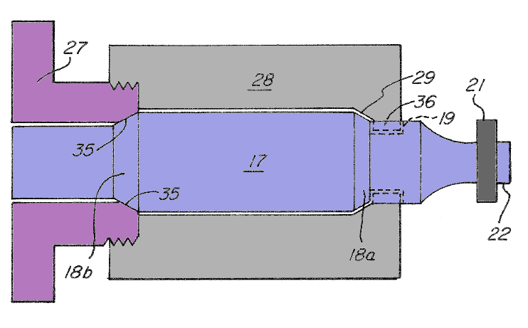
- 在另一种安装布置中,Patrikios[1] 专利 8,113,258(图 8)同时限制焊接端头的横向和侧向挠曲。壳体(28)刚性地安装在全波变幅杆(17)上的两个波节(锥部 18a 和 18b)之间。这取消了极轴安装座中稍显柔性的膜片及相关的连接结构,否则会增大弯曲柔度。
- 为变幅杆和/或增幅杆选用高刚度材料。例如,钢的杨氏模量几乎是钛的两倍。但请注意,钢在高振幅下损耗较大,必须加以考虑。也可以使用 Monel(蒙乃尔合金)。
- 为隔振膜片选用高刚度材料。通常使用钛,但如果疲劳寿命可以接受,也可以改用钢。(最初的极轴安装膜片是按 20 kHz 下 10 微米峰值振幅设计的。然而,当时没有借助有限元分析进行应力分析(Culp[0]),因此安全系数未知,但可能很大。)
上述内容说明,横向驱动焊机完全可以采用非常刚性的安装座。因此,只要设计得当以限制挠曲,横向驱动系统在承受高夹紧力的能力方面并不天然劣于 Wedge-reed 系统。
|
||||||||||
|
|
|
|
夹紧力示例
所需的夹紧力取决于具体应用。下面给出一些选定的示例。
焊接端头振幅的可调性
横向驱动系统允许使用不同增益的变幅杆和增幅杆。这样就可以通过这些部件以机械方式调整焊接端头的振幅(而不是通过电源调整),从而在需要时让电源以接近满功率运行。Wedge-reed 系统似乎不允许这类替代配置。
焊接面通常(但非必然)带有锯齿花纹,以便"咬住"金属工件。存在的问题包括焊接面与工件之间的粘附("粘连")以及锯齿的磨损。由于 Wedge-reed 系统振幅较低,这些问题可能得到缓解。
安装设置
大多数横向驱动系统使用可更换的垫圈式端头(图 4)或带整体焊接面的变幅杆(图 4),而不是竖直取向、通过拧入、压入或类似方式安装的端头(图 3,零件 40)。当这类系统中的焊接面需要清理或更换时(例如因粘连或磨损),新焊接面最初通常不会与工件表面平行。如果这种定向偏差很大,则必须将整个超声叠堆绕其轴线旋转,以获得正确的取向。(对于可更换垫圈式端头,可以通过在安装时使用对中夹具来减轻这一问题。或者,可以将端头与变幅杆键连接 — 见 Patrinkios[2] 专利 8,113,258。)相比之下,Wedge-reed 端头的焊接面始终与砧座平行,因此更换端头时无需调整。
Wedge-reed 焊接端头带有外莫氏锥度,压入竖直簧片上的内锥孔中。(莫氏锥度具有自锁性,锥角约为 3°。)因此在安装过程中,端头可以绕其轴线旋转以对正砧座的定位夹具。这使得夹具可以相对于操作者或工件调整到最佳位置。对于横向驱动系统,端头相对于变幅杆的取向是固定的,因此定位夹具必须相对于固定的端头来定向,这可能不是定位夹具的最佳取向。
可达性
喉深。Wedge-reed 焊机在焊接端头与砧座之间采用 C 形钳式布置。这种 C 形钳的喉深可以做得相当大(仅受刚度考虑的限制),因此可以焊接横向尺寸较大的零件(如板材零件)。事实上,如果焊接头和砧座安装在各自独立的滑车上,工件尺寸将仅受滑车行程长度的限制。在横向驱动系统中,工件的横向尺寸受变幅杆或隔振安装座可能干涉的限制。
伸入深度。如果必须在型腔内部进行焊接(例如在罐底),则 Wedge-reed 焊机凭借其较大的伸入深度具有优势。(这以横向驱动系统的焊接面未按弯曲振动设计为前提 — 例如图 9 的微焊机。)从理论上讲,只需在簧片上增加额外的弯曲半波,即可增大 Wedge-reed 焊机的伸入深度。
|
|
|
维护与磨损
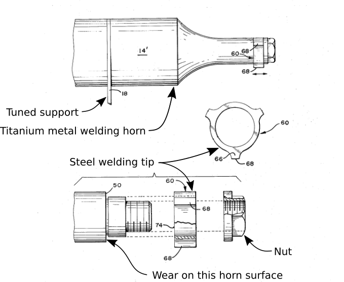
对于图 5 的横向驱动系统,变幅杆通常由 Ti-6Al-4V 制成。在高超声焊接负载下,变幅杆上与端头焊接瓣相邻的表面可能会劣化。Branson Ultrasonics 通过将材料从 Ti-6Al-4V 更换为 Ti-7Al-4Mo 缓解了这一问题。另一种解决方案是用淬硬钢变幅杆替代钛变幅杆。
或者,横向驱动系统可以采用带整体焊接面的实心钢变幅杆(如图 4)。但这样一来,当焊接面磨损到无法修复时,就必须更换整个变幅杆。Wedge-reed 系统不存在这些问题,因为端头和簧片均由淬硬钢制成,且锥配合端头可以方便地更换。
适应性
增加轴承和滑环后,横向驱动系统可以改装为旋转焊机(图 10)。Wedge-reed 系统则无法实现这一点。
焊缝长度。
工装
工装材料
良好的工装材料应具备以下特性 —
- 高耐磨性。高耐磨性通常表现为高韧性与高硬度的结合。这些性能必须在焊接高温下得以保持。
- 不粘连。工装不应与工件粘连或结合。(这部分取决于工装工作面的设计 — 例如锯齿花纹。)
- 合理的损耗。如果端头工装与变幅杆是一体的(图 4),则变幅杆在焊接振幅下的损耗必须合理。(参见钢的损耗。)
注意,工装性能既取决于工装材料本身,也取决于其与工件材料的相互作用。因此,与某种工件材料配合良好的工装,未必能与另一种工件材料配合良好(见表 1)。关于硬度,Bloss[1](第 96 页)发现:"所需工装硬度与焊接材料硬度之间的关系并不明确。"例如,考虑 SS 304 工件的焊接(表 1)— 锻态钨(HV 356)的表现为"一般",而 M2(HV 926;硬度为其 2.6 倍)的表现却为"差"。
下面一节讨论几种已就其磨损与粘附性能进行过超声工装评估的材料。这份材料清单并不全面,因此其他(可能更好的)材料也可能适用。
表 1 汇总了 Bloss[1](第 89 页)所研究的各种工装材料的磨损与粘附情况。
|
||||||||||||||||||||||||||||||||||||||||||||||||||||||||||||||||
|
表注 —
- 除另有注明外,以下引用均出自 Bloss[1],更多信息见该文献。Bloss 指出:"由于各工具所焊材料不同、试验中采用的焊接参数不同,以及每个工具所承受的焊接循环次数不一致,很难比较这些工具的性能。"
- HV = 维氏硬度;见 Bloss 表 3,第 46 页。
- 斜体材料已显示出良好前景,或已用于搅拌摩擦焊(FSW),其要求与超声金属焊接相近。
- AISI M2(5% Mo、6% W、2% V)因其高硬度和良好的耐磨性而成为最常用的工装材料。然而,M2 中的钒成分容易与铝工件形成化合物,从而加剧端头粘连。此外,焊接钛等先进材料时,M2 工具磨损很快,且容易与某些材料结合。(第 28、70 页)从 1200°C 淬火硬化至 60-65 RC;不回火。(第 61 页)HV 926。
- 350M = AISI 18Ni 马氏体时效钢(18% Ni、12% Co、4.8% Mo)。在焊接 AHSS(先进高强度钢)和 UHSS(超高强度钢)时,350M 制成的端头比 M2 具有更好的寿命和耐磨性。(第 28 页)焊接工业纯(CP)钛时表现良好,但与其他工件材料焊接时存在端头粘连问题。(第 71 页)在 500°C 下沉淀硬化 8-12 小时。(第 61 页)HV 778。
- Elkon 100W = 纯钨粉压制烧结锭,随后经轧制和旋锻加工。(第 45 页)钨颗粒之间的结合强度不足。(第 76 页)HV 432。
- 锻态钨 = 纯锻造钨,由于变形量和机械加工量增大,其强度和延性优于 Elkon 100W。(第 45 页)然而,纯钨在室温下的延性仍然较差(第 27 页),因此又试用了 W‑25Re 和 W‑La 合金。HV 356。
- W‑25Re = 钨-25% 铼。与纯钨相比延性和强度有所提高。(第 27 页)具有极高的强度和耐腐蚀性。(第 45 页)HV 509。
- W‑La = 专利钨-镧合金。得益于合金元素以及更多的锻造和旋锻加工,其延性似乎有所改善。(第 86 页)HV 440。
- 钨及其合金价格昂贵,且难以用常规方法加工。此外,这些材料密度很高,整体式端头会太重,无法在超声焊接设备允许的频率范围内工作。出于这些原因,将这些材料制成小镶块钎焊到 M2 焊接端头毛坯上。(第 59 页)然而,钎焊接头存在问题。(第 90 页)W‑La 镶块最初用 Incusil ABA 钎焊箔钎焊,但钎焊接头在焊接过程中失效。后来的镶块改用 BNi‑9(一种更高温度、更高强度的钎焊合金)钎焊,效果更令人满意。(第 104 页)
- T1 工具钢(上表未列出)也经过了测试,但其性能不及 350M 工具钢。(第 28 页)
- 陶瓷硬度很高,但韧性差。(第 30 页)
Sonobond 向 Stittsworth[1](第 12 页)推荐用 Udimet 700 焊接(与铝和铜相比)"较硬"的材料。砧座淬硬至 HRC 60–64(第 30 页)。(注意 — 这一 1973 年的建议可能已经过时。)
Branson 的韧性"陶瓷"镶块。
工装花纹
滚花。Bloss[1](第 27 页)建议,对于较厚规格的先进合金焊接,采用约为材料厚度 ½ 的(双向)滚花花纹。所得凸滚花(棱锥)的尖点被磨平。在滚花底部添加小圆角以改善疲劳性能。(第 71 页)
Liesegang[1A] 评估了用于钛材旋转缝焊的棱锥形滚花和单向滚花。对焊接过程中滚花应力的有限元分析表明,单向滚花的平均 von Mises 应力是棱锥形滚花的三倍。(第 11 页)棱锥形端头滚花在焊接试样中也获得了更高的接头强度。(第 15 页)
纹理。Bloss[1](第 89 页)提出,在可以施加高夹紧力的场合(即焊接功率充足、不会发生失速的场合),也许可以采用无滚花工具。这样可以更好地控制磨损,并且可以定期修磨端头。Bloss 还报告说,圆顶形端头通常是合适的,其圆顶半径应为试样厚度的 50 至 100 倍。
Stittsworth[1](第 12、25 页)使用电火花加工(EDM)制作带纹理的焊接面(250 RMS 光洁度)。所得端头用于 Sonobond 的 Wedge-Reed 设备,焊接薄(约 0.13 mm)铜、铝带材和导线。
机加工
某些工装材料可能难以用"常规"方法加工。对于这些材料,Bloss[1] 采用了激光加工、磨削和 EDM(电火花加工)。
焊接振幅
Bloss — 58 微米
缝焊
本文中,缝焊定义为变幅杆与工件彼此相对运动、从而形成连续或半连续焊缝的焊接方式。在典型布置中,整个超声叠堆旋转,由圆柱盘形或圆柱形变幅杆完成焊接。不过,也可以采用不旋转的变幅杆,尤其是焊接箔材时。设备可以设计成变幅杆在工件上方移动,也可以让工件在固定的变幅杆下方移动,类似于缝纫机的工作方式。焊缝可窄可宽。
如果超声叠堆必须旋转,则横向驱动系统可以通过增加轴承和电滑环来改装(例如图 10)。Wedge-reed 系统无法改装。
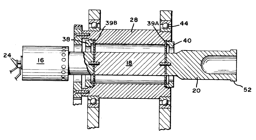
注意 — 缝焊要求焊接面的径向跳动保持相当小。在图 10 的极轴安装设计中,由于变幅杆(52)与膜片(39a)之间以及膜片(39a)与壳体(28)之间各界面存在公差累积,这一点较难做到。图 8 的设计取消了膜片,更为适合。
|
|
|
|
||||||||||||||||||
|
如果上层工件相对较薄(例如箔材),则变幅杆的焊接面可以是光滑的,也可以带有轻微的蚀刻或纹理图案。对于较厚的工件,变幅杆的焊接面可能需要更具"侵略性"的花纹。
变幅杆
在叠堆设计成旋转的场合,变幅杆既可以是常规谐振器的改型,也可以按某种弯曲模态振动来设计。
另请参阅 — 超声增材制造(UAM)。
附录 A:20 kHz 金属焊接端头尺寸
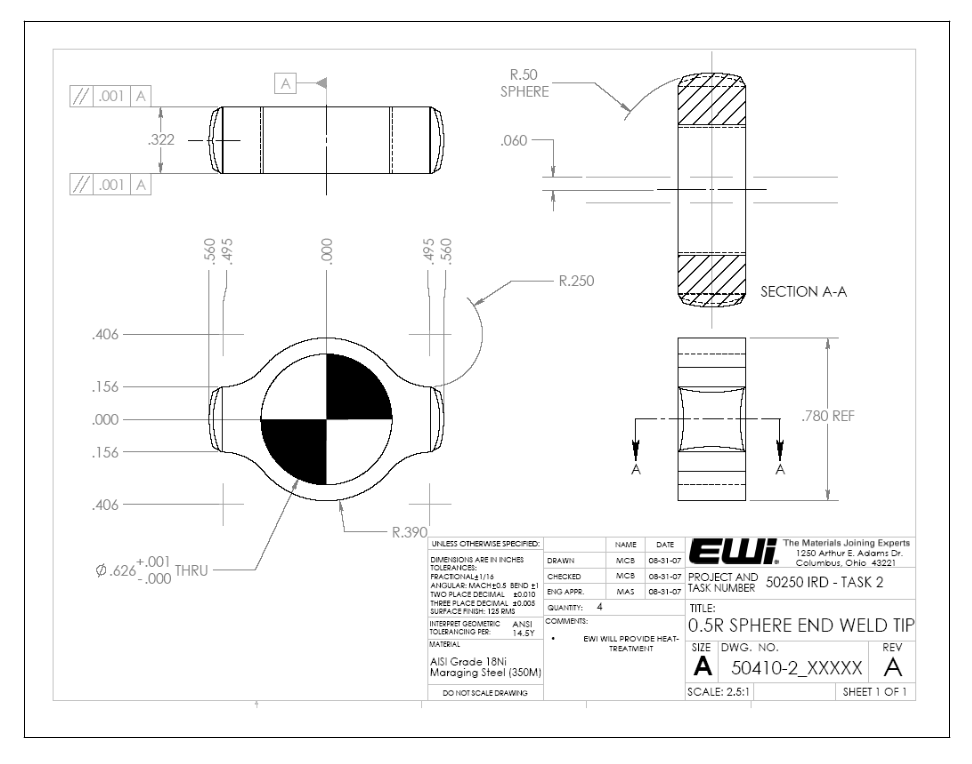
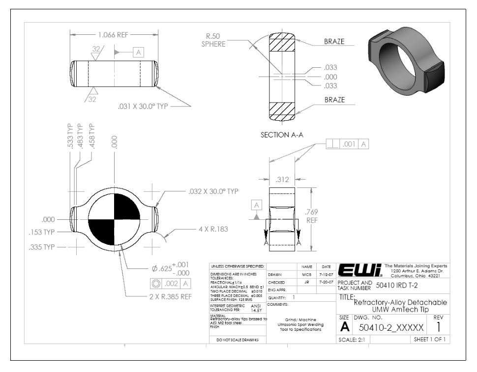
本附录给出图 5 所示 Holze[1] 专利 3,813,006 的典型 20 kHz 金属焊接端头尺寸(引自 Bloss[1])。端头的滚花花纹和焊接瓣形状取决于具体的焊接应用。
|
|
|
|
|
|
Metal welding (ultrasonic)
Contents
- Figures
- Figure 1. Ultrasonic metal welders — typical equipment configurations
- Figure 2. Replaceable metal welding tip for Wedge-reed welder
- Figure 3. Lateral drive metal welding horn supported by two vertical members
- Figure 4. Lateral drive steel metal welding horn with integral welding surface
- Figure 5. Lateral drive metal welding horn with replaceable washer tip
- Figure 6. Polar mount for lateral drive metal welder
- Figure 7. Rigid mount using flexure diaphragm and restraining collar
- Figure 8. Rigid mount using nodally mounted shell
- Figure 9. Microbonder (typically > 60 kHz)
- Figure 10. Polar mount seam welder
- Figure A1. Dimensions for replaceable metal welding washer tip
- Figure A2. Dimensions for replaceable metal welding washer tip with brazed wear insert
Ultrasonic metal welding is a process of joining two metal parts by applying ultrasonic vibration in a shear (scrubbing) mode. The ultrasonic vibration displaces the surface oxides and contaminates at the interfaces of the two parts, thereby allowing intimate metal-to-metal contact from which the weld occurs. The weld temperature is relatively low and does not involve melting.
Ultrasonic metal welding is most suited for softer metals (aluminum, copper, brass, etc.) although somewhat harder materials (e.g., titanium) can also be welded. Dissimilar materials can be welded (e.g., copper to aluminum) if their hardness is somewhat similar. Ultrasonic metal welding may be used with materials that have high electrical conductivity for which resistance welding is not well suited.
Spot welding
Figure 1 (Al‑Sarraf[1], p. 9) shows two basic metal welding configurations — the Wedge-reed system and the lateral drive system.
|
|
|
Wedge-reed system
The Wedge-reed system was developed by Aeroprojects (Jones[4] patent 2,946,119, 1960) and is currently used by Sonobond Ultrasonics (Aeroprojects successor). This system's drive consists of a horizontally mounted transducer and wedge horn; The horn is brazed to a vertically-mounted resonant reed. The horn excites the reed in flexure which, in turn, drives a replaceable taper-fit welding tip (figure 2) at the free end of the reed. The required welding force is applied to a mass located at the opposite end of the reed.
Depending on the application, the system can be designed with two colinear opposing reeds, one of which acts as the anvil. These operate at anti-phase thereby effectively doubling the welding amplitude and available power.
This system operates with relatively high force and low amplitude.
|
|
|
Lateral drive system
After developing the Wedge-reed system, Aeroprojects subsequently developed the lateral drive system (Jones[5] patent 3,209,447, 1965). Branson Ultrasonics later developed a lateral drive system with flexurally resonant support members at the antinodes (Shoh[1] patent 3,752,380, 1973, figure 3). Further developments and variations of this system (particularly in the mounting arrangements) are used today.
|
|
|
The horn may be solid (typically hardened steel, figure 4) or may have a replaceable multi-lobed welding tip (Holze[1] patent 3,813,006; see figure 5 and Appendix A; see setup). The ultrasonic stack is often mounted in some type of cylindrical shell (e.g., the polar mount of figure 6) that allows rotation about the stack (polar) axis so that the multi-lobed tip can be properly oriented with respect to the workpiece. Because of its axial symmetry, this arrangement also adapts well to seam welding. (Note — The booster in figure 6a is shown in an incorrect orientation. The stud should be facing the transducer.)
Dual drive
|
|
|
|
|
|
|
||||||||||
|
System comparisons
Weld quality
Weld quality is determined by many factors (importantly, including the process control by the power supply which is beyond the scope of this discussion). One area in which the two systems differ somewhat is the application of the tip motion. In both systems the tip applies shearing motion to the work pieces. However, in addition the Wedge-Reed tip also has some rocking motion due to the flexure of the reed. It is not known to what extent this may impact (posibly improve) the weld quality.
Amplitude collapse?
Clamping force
According to Sonobond's product literature, "The Wedge-Reed system features low vibratory amplitude and high vibratory force, suitable for welding metals." By comparison, "The lateral drive system is characterized by high vibratory amplitude and low vibratory force, appropriate for welding plastics." "Because of [the lateral system's] cantilevered approach, clamping force is applied some distance from the weld, resulting in a bending moment on the coupler that limits static force. This makes the lateral drive system incapable of producing acceptable welds for tinned or oxidized wires and terminals."
Note — A lateral drive system is characterized by the orientation of the horn with respect to the welded part, not the method by which the horn is supported.
Lateral drive support systems
The Shoh patent 3,752,380 (figure 3) shows a lateral drive system where the horn (16) with welding tip (40) is supported between two vertical (flexurally resonant) members (30 and 32). In this arrangement there is no bending moment on the tip. Therefore, the allowed clamping force is only limited by the strength of the support members. (Also see — Jones[5] patent 3,209,447 which addresses the same issue; Roberts[3] patent 6,078,125 discussed here.)
In a lateral drive system where the horn is cantilevered (figure 1, bottom; figure 5), the clamping force will cause the welding tip to deflect vertically and possibly horizontally. Because of the cantilever, the vertical deflection will tilt the tip's welding surface slightly with respect to the anvil (like opening a pair of scissors). The amount of deflection and resulting misalignment will depend on the rigidity of the stack and support structure and also on the clamping force.
For many applications (e.g., tube sealing) this deflection will not cause problems. Also, if the tip is radiused then this may not be a problem since the tip is essentially self-orienting. However, some applications such as wire splicing and wire termination may require more critical alignment. For example, Patrikios[1] patent 8,113,258 states that "the position of the weld tip must be maintained within 3 microns (0.001 inches)" (column 1, line 42). (Note that 3 microns (3*10-6 m) translates to 0.0001 inches, not 0.001 inches, so the specified requirement is unclear. However, either requirement is fairly tight.)
When the horn is cantilevered, there are methods to reduce the horn's vertical deflection.
- Use a very rigid support. For example, Patrinkios[1] patent 5,772,100 (figure 7) show a design with a collar (102) that rests on the horn's node via surface 108. This collar is held stationary so that surface 108 restricts the horn's vertical deflection. The collar is ultrasonically isolated from the horn by a diaphragm (100) at the horn's antinode, similar to the polar mount diaphragm of Shoh[3] patent 3,955,740. (Interestingly, the Partikios patent doesn't site the Shoh patent as prior art.) Like the polar mount, this design doesn't restrict the lateral (axial) movement of the horn. Compared to the polar mount, this design has three additional advantages —
- In the polar mount the booster must be tuned to fit within the length of the shell or, alternately, the shell must be shimmed to fit the existing booster length. Since the Patrikios design does not use a rear diaphragm, its booster length is not restricted. Thus, any off-the-shelf booster can be used.
- In the polar mount the booster diameter is limited by the inside diameter of the shell. Since the Patrikios design does not have a shell surrounding the booster, its diameter is unrestricted.
- Because only one anti-nodal diaphragm is needed, the booster could be eliminated and the stack can be shorter. This assumes that the horn's gain is sufficient to give the required welding amplitude when the horn is driven directly by the transducer.
- On the other hand, if this design is as shown in figure 7 (i.e., where any surface behind surface 108 exceeds the diameter of 108) then the horn can only be replaced by entirely disassembling the collar from the diaphragm. Because the polar mount does not have a collar around the horn, the horn can be easily replaced and any diameter horn can be used.
- In another mounting arrangement the Patrikios[1] patent 8,113,258 (figure 8) restricts both the transverse and lateral deflection of the welding tip. The shell (28) mounts rigidly between two nodes (tapers 18a and 18b) on a full-wave horn (17). This eliminates the somewhat flexible diaphragms of the polar mount and the associated joints which otherwise contribute to the bending compliance.
- Use a stiff material for the horn and/or booster. For example, Young's modulus for steel is almost twice that of titanium. Note, however, that steel is lossy at high amplitudes so this must be considered. Monel might also be used.
- Use a stiff material for the isolation diaphragms. Titanium has normally been used but steel could be substituted if its fatigue life is acceptable. (The original polar mount diaphragms were designed for 10 microns_peak amplitude at 20 kHz. However, this was done without the benefit of FEA for stress analysis (Culp[0]) so the factor of safety is unknown but could be large.)
The above illustrate that very rigid mounts of lateral drive welders are possible. Hence, with proper design to limit deflections, the lateral drive system is not inherently inferior to the Wedge-reed system in its ability to accept high clamping force.
|
||||||||||
|
|
|
|
Clamping force examples
The required clamping force will depend on the application. The following are some selected examples.
Adjustability of welding tip amplitude
The lateral drive system allows horns and boosters of various gains to be used. This allows the amplitude of the welding tip to be mechanically adjusted via these components (rather than through the power supply) so that the power supply can operate at near full power, if needed. The Wedge-reed does not appear to allow these types of alternate configurations.
The welding surfaces are typically (but not necessarily) serrated in order to "grab" the metal workpiece. Problems include adhesion of the welding surfaces to the workpiece ("sticking") and wear of the serrations. These problems may be mitigated in the Wedge-reed system because of its lower amplitude.
Setup
Most lateral drive systems use a replaceable washer tip (figure 4) or a horn with an integral welding surface (figure 4) rather than a vertically oriented tip (figure 3, object 40) that is screwed in, pressed in, or similarly attached. When the welding surface in such systems needs to be cleaned or replaced (e.g., because of sticking or wear), the new welding surface will generally not be initially parallel to the workpiece surface. If this mis-orientation is substantial then the entire ultrasonic stack must be rotated about its axis in order to obtain the proper orientation. (For the replaceable washer tip, this problem can be reduced by using an alignment fixture during installation. Alternately, the tip can be keyed to the horn — see Patrinkios[2] patent 8,113,258.) In contrast, the welding surface of the Wedge-reed tip is always oriented parallel to the anvil so no adjustment is needed when the tip is replaced.
The Wedge-reed welding tip has a male Morse taper that is pressed into a female mating taper in the vertical reed. (A Morse taper is self locking with an included angle of approximately 3°.) During installation the tip can therefore be rotated about its axis to align to the anvil's nest fixture. This allows the fixture to be oriented to the best position with respect to the operator or workpiece. For the lateral drive system, the tip's orientation is fixed with respect to the horn so the nest fixture must be oriented with respect to the fixed tip. This may not be the optimum orientation of the nest fixture.
Accessibility
Throat depth. The Wedge-reed welder has a C-clamp style arrangement between the welding tip and the anvil. The throat depth of this C-clamp can be made quite large (subject only to rigidity considerations) so parts with large lateral dimensions (e.g., sheet parts) can be welded. In fact, if the welding head and anvil were mounted on separate trollies then the workpiece size would be limited only by the travel length of the trolly. In the lateral drive system the lateral part size is limited by possible interference with the horn or the isolation mounts.
Reach. If welding must take place inside a cavity (e.g., at the bottom of a can) then the Wedge-reed welder has an advantage due to its extended reach. (This assumes that the welding surface of the lateral drive system is not designed to vibrate in flexure — e.g., per the microbonder of figure 9.) In theory the reach of the Wedge-reed welder could be increased simply by adding additional flexural half-waves to the reed.
|
|
|
Maintenance and wear
For the lateral drive system of figure 5, the horn is typically made of Ti-6Al-4V. Under high ultrasonic welding loads the horn's surface adjacent to the tip's welding lobe can deteriorate. Branson Ultrasonics has mitigated this problem by changing from Ti-6Al-4V to Ti-7Al-4Mo. Another solution is to substitute a hardened steel horn for the titanium horn.
Alternately, the lateral drive system could use a solid steel horn with an integral welding surface (per figure 4). Then, however, the entire horn must be replaced when the welding surface becomes worn and can no longer be salvaged. The Wedge-reed system does not have these problems since both the tip and reed are made from hardened steel and the taper-fit tip can be easily replaced.
Adaptability
With the addition of bearings and slip rings, the lateral drive system can be converted to a rotary welder (figure 10). This is not possible with the Wedge-reed system.
Weld length.
Tooling
Tooling materials
Good tooling materials should have the following characteristics —
- High wear resistance. High wear resistance is typically characterized by a combination of high toughness and high hardness. These properties must be preserved at the elevated welding temperatures.
- Non-adhesion. The tooling should not stick or bond to the workpieces. (This may depend, in part, on the design of the tooling working surfaces — e.g., the serrations.)
- Reasonable loss. If the tip tooling is integral to the horn (figure 4) then the horn loss must be reasonable at the welding amplitude. (See steel loss.)
Note that the performance of the tooling depends on both the tooling material and its interaction with the workpiece material. Hence, tooling that works well with one workpiece material may not necessarily work well with another workpiece material (see table 1). Regarding hardness, Bloss[1] (p. 96) found that, "The relationship of the required tooling hardness to the welding material hardness is not well defined." For example, consider welding of SS 304 workpieces (table 1) — wrought tungsten (HV 356) had "fair" performance whereas M2 (HV 926; 2.6x hardness) had "bad" performance.
The following section discusses several materials that have been evaluated for the ultrasonic tooling with regard to wear and adhesion. This list of materials is not comprehensive so other (possibly better) materials may also be available.
Table 1 gives a summary of wear and adhesion for various tooling materials that were investigated by Bloss[1] (p. 89).
|
||||||||||||||||||||||||||||||||||||||||||||||||||||||||||||||||
|
Table notes —
- References below are from Bloss[1] unless otherwise noted. See additional information there. Bloss notes, "It is difficult to compare the performance of the tools because of the different materials they were used to weld, the different welding arameters used during the trials, and an inconsistent number of weld cycles applied to each tool."
- HV = Vickers hardnesses; see Bloss table 3, p. 46.
- Italicized materials have shown promise or are used in friction stir welding (FSW) whose requirements are similar to ultrasonic metal welding.
- AISI M2 (5% Mo, 6% W, 2% V) is the most commonly used tooling material because of its high hardness and good wear resistance. However, the vanadium component in M2 readily forms compounds with aluminum workpieces thus promoting tip-sticking. Also, when welding advanced materials such as titanium, M2 tools wear quickly and readily bond to some of the materials. (pp. 28, 70) Hardened to 60-65 RC by quenching from 1200°C; not tempered. (p. 61) HV 926.
- 350M = AISI grade 18Ni maraging steel (18% Ni, 12% Co, 4.8% Mo). Tips constructed of 350M had improved life and wear resistance over M2 while welding AHSS (Advanced High-Strength Steels) and UHSS (Ultra High-Strength Steels). (p. 28) It performed well when welding commercially pure (CP) titanium but tip stickage was a problem with other workpiece materials. (p. 71) Precipitation-hardened at 500°C for 8-12 hours. (p. 61) HV 778.
- Elkon 100W = pure tungsten powder ingots that are pressed and sintered followed by rolling and swaging. (p. 45) The strength of the bond between the tungsten particles was not sufficient. (p. 76) HV 432.
- Wrought-W = pure wrought tungsten with improved strength and ductility over Elkon 100W because of increased deformation and mechanical working. (p. 45) However, pure tungsten still has poor ductility at room temperature (p. 27) so the W‑25Re and W‑La alloys were tried. HV 356.
- W‑25Re = tungsten-25% rhenium. Improved ductility and strength over pure tungsten. (p. 27) Extreme strength and corrosion resistance. (p. 45) HV 509.
- W‑La = proprietary tungsten-lanthanum alloy. It appears to have improved ductility due to the alloying elements and increased forging and swaging. (p. 86) HV 440.
- Tungsten and its alloys are costly and difficult to machine by conventional means. Also, these materials have high density so a full tip would have been too heavy to operate within the allowed frequency range of the ultrasonic welding equipment. For these reasons, small inserts of these materials were brazed onto M2 welding tip blanks. (p. 59) However, the brazed joints were problematic. (p. 90) W‑La inserts were initially brazed with Incusil ABA braze foil but the brazed joints failed during welding. Later inserts were brazed with BNi‑9 (a higher-temperature, higher-strength braze alloy) which proved more satisfactory. (p. 104)
- T1 tool steel (not shown above) was tested but its performance was inferior to 350M tool steel. (p. 28)
- Ceramics have very high hardness but poor toughness. (p. 30)
Sonobond recommended Udimet 700 to Stittsworth[1] (p. 12) for welding "harder" materials (compared to aluminum and copper). The anvil was hardened to HRC 60–64 (p. 30). (Note — this 1973 recommendation may be outdated.)
Branson's tough "ceramic" insert.
Tooling patterns
Knurls. Bloss[1] (p. 27) suggests a knurl pattern (bi-directional) of approximately ½ the material thickness for welding advanced alloys in thicker gauges. The points of the resulting male knurls (pyramids) are flattened. A small radius was added to the bottom of the knurl to improve fatigue properties. (p. 71)
Liesegang[1A] evaluated a pyramidal knurl and a unidirectional knurl for rotary seam welding of titanium. FEA of knurl stresses during welding showed that the averaged von Mises stress with a unidirectional knurl were three times higher than with a pyramidal knurl. (p. 11) The pyramidal tip knurl also gave higher joint strength in the welded specimens. (p. 15)
Textures. Bloss[1] (p. 89) suggests that a non-knurled tool might be possible in situations where high clamping forces are possible (i.e., where sufficient welding power is available so that stalling is avoided). Then the wear could be better controlled and the tip could be periodically refinished. Bloss also reports that dome-shaped tips are often suitable, where the dome radius should be 50 to 100 times the specimen thickness.
Stittsworth[1] (pp. 12, 25) used EDM (electrical discharge machining) to create textured welding surfaces (250 RMS finish). The resulting tips were used in Sonobond's Wedge-Reed equipment to weld thin (~0.13 mm) copper and aluminum strips and wires.
Machining
Some tooling materials may be difficult to machine by "conventional" means. For these materials Bloss[1] used laser machining, grinding, and EDM (electrodischarge machining).
Welding amplitudes
Bloss - 58 microns
Seam welding
As used here, seam welding is defined as a weld in which the horn and workpiece move relative to each other in order to create a continuous or semi-continuous weld. In the typical arrangement the entire ultrasonic stack rotates as a cylindrical disk or cylindrical horn performs the welding. However, a non-rotating horn also may be possible, especially for welding foils. The equipment may be designed so that the horn moves across the workpiece or the workpiece may move under a stationary horn, similar to the operation of a sewing machine. The weld can be narrow or broad.
If the ultrasonic stack must rotate then a lateral drive can be adapted by adding bearings and electrical slip rings (e.g., figure 10). The Wedge-reed can not be adapted.
Note — Seam welding requires that the runout of the welding surface should be kept reasonably small. This is somewhat difficult in the polar mount design of figure 10 because of the tolerance stackup of the interfaces between the horn (52) and diaphragm (39a) and between the diaphragm (39a) and shell (28). The design of figure 8, which eliminates the diaphragms, is more suitable.
|
|
|
|
||||||||||||||||||
|
If the top workpiece is relatively thin (e.g., foils) then the horn's welding surface can either be smooth or may have a light etch or texture pattern. For thicker workpieces the horn's welding surface may need to be more agressive.
Horns
Where that stack is designed to rotate, horns may either be adaptations of conventional resonators or may be designed to vibrate in some flexural mode.
Also see — Ultrasonic Additive Manufacturing (UAM).
Appendix A: 20 kHz metal welding tip dimensions
This appendix shows typical 20 kHz metal welding tip dimensions for the Holze[1] patent 3,813,006 of figure 5 (from Bloss[1]). The tip's knurl pattern and shape of the welding lobe will depend on the particular welding application.
|
|
|
|
|
|