钢的性能
目录
- 插图
- 图 1. 带整体式焊接面的钢制金属焊接变幅杆
- 图 2. 抗冲击性能对比图
- 图 3. 15 kHz 下声学材料的功率损耗
- 图 4. 损耗测量试验装置(Aeroprojects)
- 图 5. 晶粒尺寸对内耗 Q-1 的影响
- 图 6. 试验钢的成分与处理
- 图 7. 温度对各种钢弹性模量的影响
- 图 8. 温度对各种结构钢弹性模量的影响
- 图 9. 相对于 W1 钢的工具钢可加工性评级
- 图 10. 常用不锈钢及其易切削对应牌号的可加工性对比
- 图 11. CPM® 钢的韧性与耐磨性对比
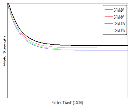
- 图 12. CPM® 变幅杆的金属焊接试验
- 图 13. 20 kHz 旋转式金属焊接变幅杆
- 图 14. 20 kHz 疲劳试样
- 图 15. Ferro-Titinat WFN、CPM Rex M4、MC90 — 20 kHz 疲劳试验结果
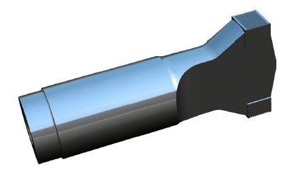
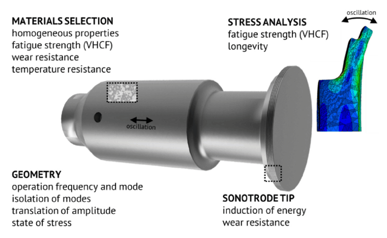
当需要耐磨性和/或抗冲击性时,超声谐振器可采用钢材。例如,钢已用于金属焊接变幅杆(焊接端头表面与变幅杆为一体 — 图 1),以及用于嵌件作业的变幅杆。
|
|
|
材料选择
与钛和铝不同,选择合适的钢要复杂得多,原因有以下几点。
- 钢有数千种之多。有些钢的合金成分仅有细微差别,但对性能的影响却很大。
- 对于可热处理钢,有许多影响性能的热处理变量,例如温度和持续时间(预热、热处理、淬火、回火)、周围介质(空气、惰性气体、盐浴)等。即使对于同一种钢,这些参数也可能因所需的最终性能不同而变化。
- 虽然钢在相对较低的应变下表现良好,但在较高应变下损耗会急剧增加(见图 3和表 1)。常规的(手册)性能列表并不给出损耗性能,因为 —
1) 损耗对于常规(非超声)应用并不重要。
2) 损耗不是固定值,而是随应变变化。
3) 损耗取决于热处理。
因此,必须针对每种材料和每种热处理状态,在预期应变水平下通过实际超声试验来确定损耗。虽然低损耗很重要,但也必须同时考虑其他所需性能,如耐磨性和缺口敏感性(例如对于螺纹)。
疲劳
参见疲劳的一般性讨论。此外,以下内容为钢所特有。
缺口敏感性
声学材料的一个理想特性是具有较低的疲劳缺口敏感性(即带缺口试样的持久强度应与同种无缺口材料几乎相等)。例如,这对螺纹的疲劳很重要。
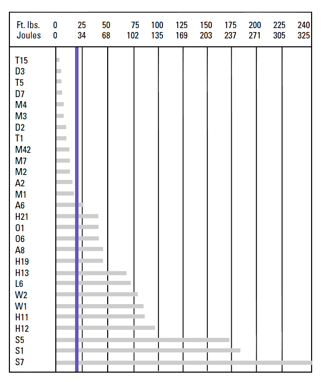
测定冲击缺口敏感性的两个类似试验是夏比(Charpy)试验和艾氏(Izod)试验。在这些试验中,一个重摆锤撞击并打断带缺口的试样。摆锤势能的变化(撞击前后)即表征冲击缺口敏感性。图 2 根据夏比 "V" 型缺口试验结果给出了各种钢的冲击抗力。(Bryson[1],第 139 页)注 — 竖直蓝线为后加,它代表 Ti-6Al-4V(退火态及 STA 态薄板和棒材)的夏比 "V" 型缺口试验结果。(见 TIMET[1],图 26,第 18 页。)(由于钛是正交各向异性的,其冲击抗力取决于试验方向。)
|
|
|
遗憾的是,冲击缺口敏感性与疲劳缺口敏感性之间可能几乎没有相关性。正如 Yen[1](第 12 页)所述:"人们普遍认为,无论是在疲劳试验、静拉伸试验还是冲击试验中,硬钢都比软钢更具缺口敏感性。一些试验数据表明,钢的强度越高,夏比冲击值越低,疲劳缺口敏感性越大;因此,人们可能会推断冲击值与疲劳缺口敏感性之间存在某种关系。然而,从未有报道表明这两类试验之间存在直接相关性,而且已有相反的证据表明没有理由期待这种相关性存在。"
螺纹
已知钢制变幅杆会在螺纹处失效。
损耗
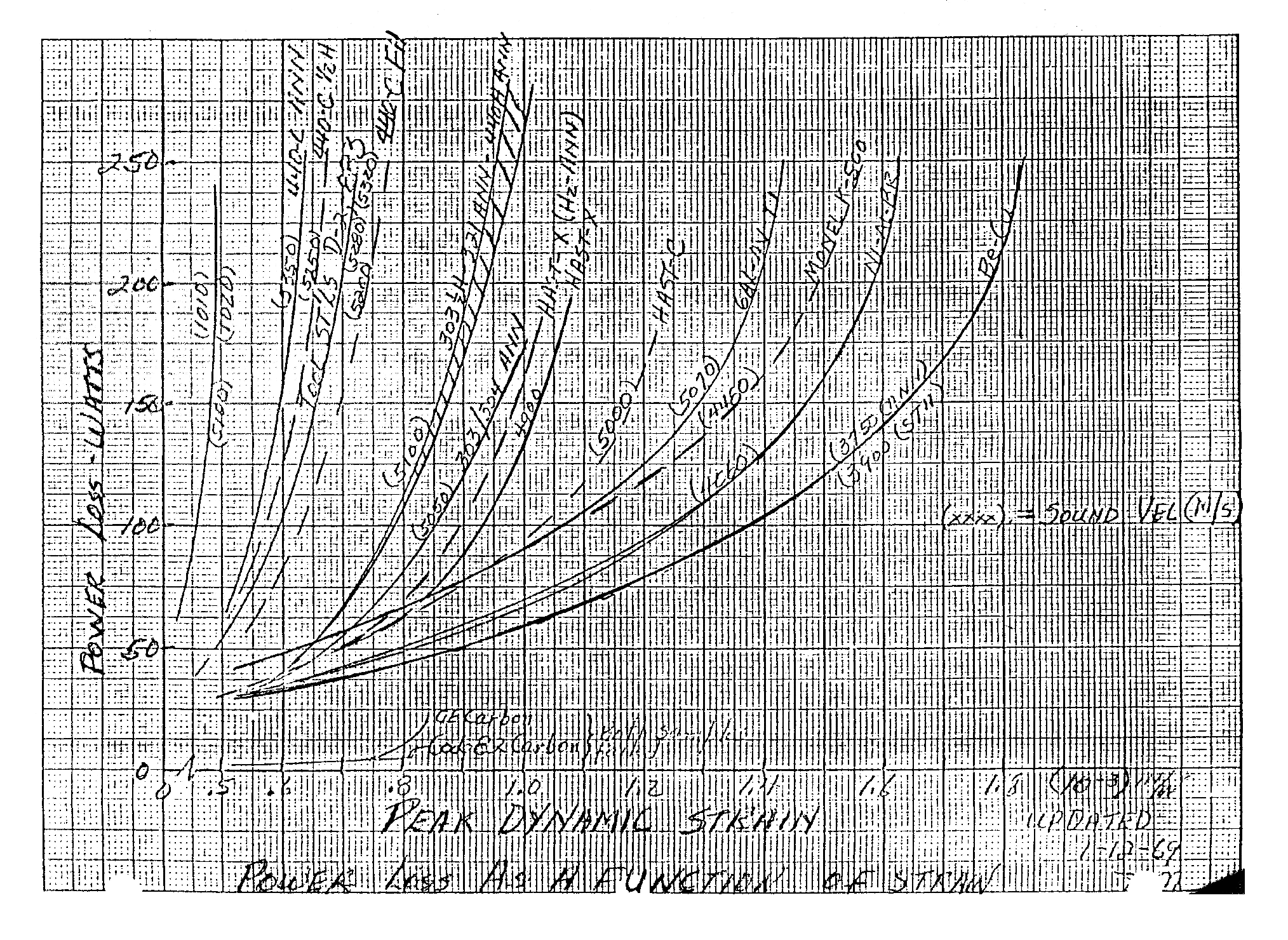
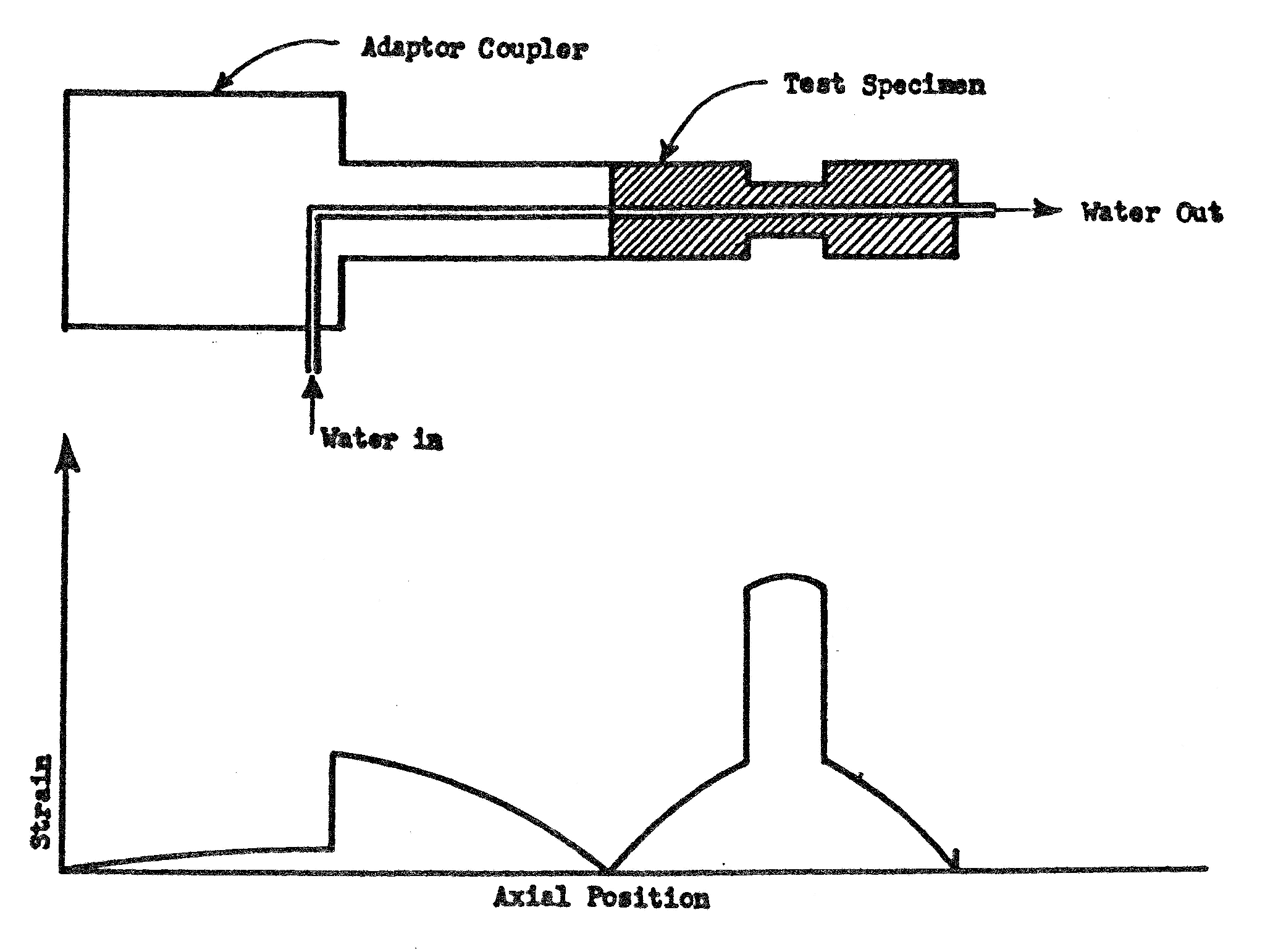
图 3给出了多种材料(包括几种钢)的损耗。(该数据来自 Aeroprojects 1969,由 Maropis[0] 转交给 Culp[0]。)试验装置见图 4。损耗根据流经一根高应力 15 kHz 变幅杆中心的水的温升来确定。注意,这些损耗仅对特定频率和试样形状有效。不过,各种材料之间的比较仍然有效。表 1 给出了对图 3 中手写标注的最佳判读结果。
注 —
- 所有钢的损耗都高于 Ti-6Al-4V,而且许多钢的损耗显著更高。
- 对于 440-C 钢,当其状态从退火变为全硬时,波速从 5350 m/sec 降至 5200 m/sec(-2.8%)。D2 表现出类似的趋势。
|
|
|
|
|||||||||||||||||||||||||||||||||||||||||||||||||||
|
|
|
|
另见不锈钢的损耗测量。
晶粒尺寸的影响
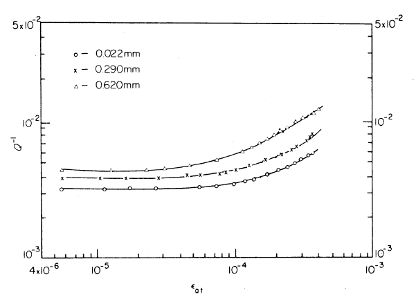
Puskar[1] 在 23 kHz 下对一种低碳非合金钢进行了测试,以测定内耗 Q-1。(注 — 损耗与内耗成正比,内耗是品质因数 Q 的倒数。)结果见图 5,其中横轴为总应变幅值 \( \epsilon_{at} \)。(据信这是峰值应变而非峰-峰应变,尽管文中未明确说明。)
随着晶粒尺寸减小(很可能源于热处理工艺),内耗也随之降低。很可能存在某个临界点,晶粒尺寸进一步减小不再带来内耗的进一步降低。但是,从所给数据中无法推断出这一点。
图 5 还表明,在达到某个临界应变 \( \epsilon_{c} \) 之前,内耗 Q-1 保持不变。超过该临界应变后,内耗开始增加(即内部损耗的增长快于储存能量)。希望 \( \epsilon_{c} \) 尽可能大,这样谐振器就能在高振幅下振动而不会遭遇意外的高损耗。图 5 表明,晶粒尺寸最小时 \( \epsilon_{c} \) 最大。例如,晶粒尺寸为 0.620 mm 时 \( \epsilon_{c} \) 为 7.3e-5,而晶粒尺寸为 0.022 mm 时 \( \epsilon_{c} \) 增至 1.3e-4。
此外,存在一个使内耗开始增加的临界应变 \( \epsilon_{c} \)(即曲线开始上翘)。该临界应变是内部损耗增长快于储存能量的应变。
\( \epsilon_{c} \) 随晶粒尺寸减小而增大。例如,晶粒尺寸为 0.620 mm 时 \( \epsilon_{c} \) 为 7.3e-5,而晶粒尺寸为 0.022 mm 时 \( \epsilon_{c} \) 增至 1.3e-4。因此,仅考虑损耗的影响,这种细晶材料相比同种粗晶材料可以在显著更高的振幅下驱动。其他钢很可能也是如此。
|
|
|
温度的影响
对弹性模量(杨氏模量)的影响
钢的弹性模量随温度升高而降低(即材料更易被压缩)。因此,在高温下工作的谐振器必须具有更短的调谐长度,以保持兼容的工作频率。
特定钢种
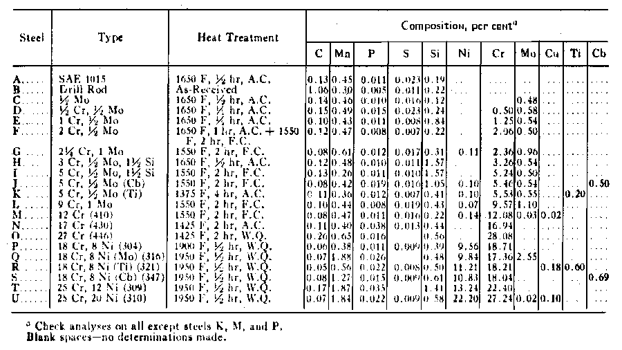
Garofalo[1] 对一系列钢进行了测试,以确定弹性模量与温度的关系。图 6 给出了这些钢的详细信息。
|
|
|
|
||||||||||||||||||||
|
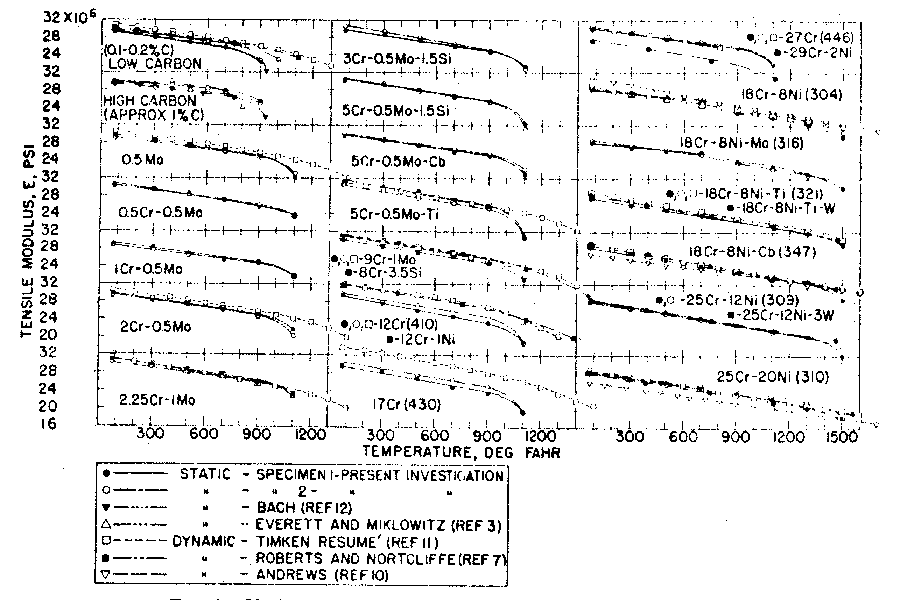
图 7(Garofalo[1],第 18 页)给出了 Garofalo 的试验结果以及其他来源的试验结果。
|
|
|
结果(第 19-20 页)—
|
||||||||||||||||||
|
注意,从图 7 可以看出,许多材料的趋势在约 900 °F (480 °C) 以上变为非线性。300 系列不锈钢通常在高达 1200 °F (650 °C) 或更高温度下仍保持合理的线性。
通用结构钢
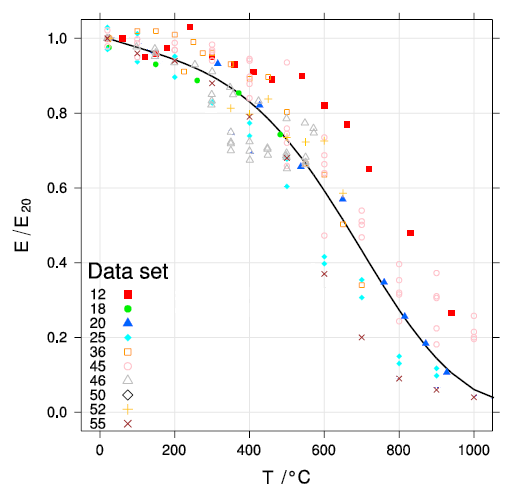
图 8(Seif[1],第 9 页)给出了来自各试验来源(数据集)的各种"结构"钢的弹性模量与温度的关系。(更多信息见 Seif[1](第 13 页)。)公式 \eqref{eq:15301a} 给出了相应的最小二乘回归曲线拟合,所依据的温度数据最高达 725 °C。
注意图 8 中数据离散度很大。因此,只有在无法获得所需材料的具体温度数据时,才应使用图 8 和公式 \eqref{eq:15301a}。
|
|
|
图注 —
- \( T \) 的单位为 °C。
- \( E_{20} \) 为 20 °C 下的弹性模量。
图 8 曲线的回归方程 —
\begin{align} \label{eq:15301a} \frac{E(T)}{E_{20}} &= \textsf{exp} \left\{ -\small\frac{1}{2} \left(\frac{T-20}{C_3}\right)^{C_1} \, -\small\frac{1}{2} \left(\frac{T-20}{C_4}\right)^{C_2} \right\} \end{align}
方程注 —
- \( T \) 的单位为 °C。
- 方程常数见表 4。(见 Seif[1],表 5‑2(最后四行),第 19 页。注意拟合常数 \(C_2\) 被强制取为 1,未进行拟合(第 11 页)。)
表 4. 公式 \eqref{eq:15301a} 的曲线拟合参数 参数 单位 数值 \(C_1\) ——— 3.768 \(C_2\) ——— 1.000 \(C_3\) °C 639 \(C_4\) °C 1650
对泊松比的影响
可加工性
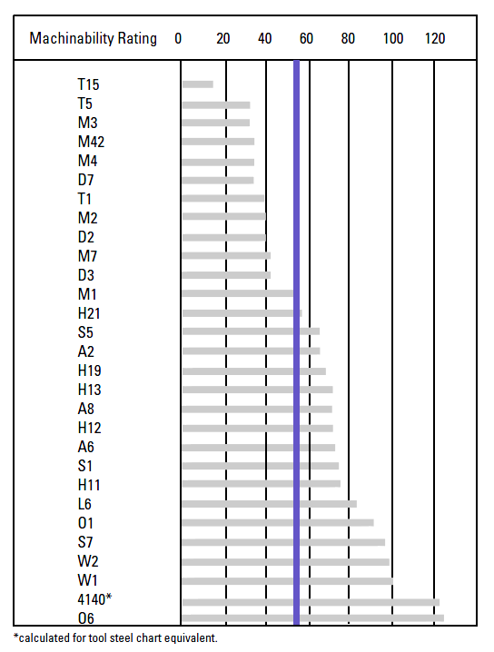
图 9 给出了各种钢相对于 W1(一种水淬硬化钢,取值为 100)的可加工性,其中 W1 的可加工性相当于 AISI B1112 标尺上的 40%。(Bryson[1],第 141 页。注 — 竖直蓝线为后加,它代表 Ti-6Al-4V 的可加工性,在 AISI B1112 标尺上为 22%(Carpenter[1],第 6 页),即相对于 W1 为 55%。)各种不锈钢的可加工性另见图 10。
|
|
|
已知钢种
以下钢种曾以某种方式用于超声谐振器。这些钢种的相对优劣目前仅部分为人所知。
|
|||||||||||||||||||||||||||||||||||||||||||||||||||||||||||||||||||||||||||||||||||||||||||||||||||||||||
|
表注 —
- HRC = 洛氏 C 标尺硬度。
- 细杆波速为计算值。
- 粗体字 — 由超声试验测得或据其计算的数据。除特别注明外,这些数据均来自 Culp[0]。相应的标称"手册"数据(通常来自制造商数据或 matweb.com)列于括号内。
- 除非另有说明,所有性能均为室温下的数值。
表的参考来源 —
- FX Temper 2 工具钢 —
泊松比通过对三个试样(25.4 mm 见方)进行拉伸试验测得。
密度在实验室测得。
- 杨氏模量通过 40 kHz 超声全波/半波试验测得(一个试样)。试样直径为 Ø19.1 mm。
- 杨氏模量通过一个 40 kHz 双槽条形变幅杆的有限元分析(FEA)标定(每种各一个试样)。
- 杨氏模量通过一个 40 kHz 无槽削平圆柱形变幅杆的有限元分析(FEA)标定。
- Al-Sarrif[1] — 20.8 kHz 金属焊接变幅杆(FEA 标定);20 微米峰-峰值(第 68 页);输入 5 微米峰-峰值。整体式焊接端头硬化至 HRC 55-60(第 54 页);尚不清楚该硬度是仅针对焊接端头还是针对整个变幅杆。
- Stanasel[1] — 用于汽车行业电缆焊接的 20 kHz 金属焊接变幅杆(图 1),FEA 分析。Stanasel 给出了变幅杆的部分尺寸。
以下材料的说明 —
- 除下文特别推荐外,常规热处理建议(未考虑超声要求)见 Bryson[1]。可咨询材料制造商或您的热处理厂商,他们可能有更多建议。
- 除非另有说明,下文的"特性"均来自制造商数据,或来自 matweb.com。
- 所列应用为已知或文献中可查到的应用。所列应用并不全面,在许多情况下,某种材料很容易用于多种应用。此外,某些应用可能属于原型开发,所选材料可能只是出于方便,而非追求最优材料。
工具钢
AISI A2 工具钢
特性 — "高淬透性,热处理中尺寸稳定性高,耐磨性、疲劳寿命、韧性和深层淬硬性能良好。"
应用 — 石油产品的超声处理。见 Gunnerman 的专利[2],第 0013 段。(注 — 该专利写的是"2‑A 工具钢",但无法确认存在这种材料。根据给定的成分(第 0013 段),该材料很可能是 A2。)
AISI D2 工具钢
特性 — 一种空冷硬化、高碳、高铬工具钢,可热处理至 HRC 60-62。由于显微组织中含有大量碳化物,它具有优异的抗磨粒磨损性能。
应用 — 超声金属焊接端头、塑料封合变幅杆、嵌件变幅杆。
AISI M2 工具钢
特性 — 一种钨钼系高速工具钢,耐磨性、韧性和热硬性组合优异。
应用 — 超声金属焊接变幅杆与端头。
达到 HRC 61-62 的建议热处理 —
- 将工件放入炉中,分三步预热以消除应力。
- 620 °C (1150 °F) 保温 30 分钟
- 840 °C (1550 °F) 保温 15 分钟
- 1040 °C (1900 °F) 保温 15 分钟
- 淬火加热温度 — 1120-1180 °C (2050-2150 °F)
- 真空淬火
- 在 540-590 °C (1000-1100 °F) 双重回火。这不会降低硬度。
Vertex
特性 — "TLS Vertex 工具钢是一种通用的高铬空冷硬化工具钢,其特点是可达到的硬度相对较高,且显微组织中含有大量富铬合金碳化物。这些碳化物使其在与其他金属和磨料滑动接触时具有良好的耐磨性。Vertex 中的主要合金碳化物比 D2 工具钢特有的大型富铬合金碳化物更小。这些较小的碳化物使 Vertex 相比 D2 具有更好的冲击韧性和更优的疲劳性能。
Vertex 中添加的钼提高了合金碳化物的硬度,更重要的是,与 D2 相比提供了更优异的二次硬化响应。因此,与 D2 不同,Vertex 可以在更高的回火温度下回火,同时仍能达到超过洛氏 C 60 的硬度。由于二次硬度更高,Vertex 在较高回火温度下回火后表现出比 D2 更优异的耐磨性,同时还具有高温回火带来的更优韧性。"(Vertex 数据表)
最初由 Timken Latrobe Steel 生产;现为 Latrobe Specialty Steels Co.。
热处理(Latrobe 建议)。最终硬度应约为 HRC 56。
- 预热。以不超过 400 °F/hr (220 °C/hr) 的速率预热至 1150 - 1250 °F (621 -677 °C),均温后加热至 1400 - 1450 °F (760 - 788 °C)。
- 奥氏体化。从预热温度缓慢加热。炉内或盐浴:在 1850 °F (1010 °C) 奥氏体化。
- 淬火。空气或加压气体。冷却至 150 - 125 °F (66 - 51 °C)。
- 回火。淬火后立即回火。加热至 1050 °F (565 °C)。每英寸厚度保温 1 小时(最短 2 小时),然后空冷至环境温度并重复一次。
FX Temper 2
特性 — "适量的镍(Ni .80%)、铬(Cr 1.15%)和钼(Mo .5%)合金元素使这种模具钢在广泛使用的 Temper 2 硬度(38-42 HRC)下实现了断裂韧性与耐磨性的良好平衡。"
由 Finkl Steel 生产。见数据表。
应用 — 焊料的超声雾化(Culp[0])。
不锈钢
AISI 630 (17Cr-4Ni; 17-4 PH) 不锈钢
PH 指沉淀硬化。
特性 — 一种马氏体沉淀/时效硬化不锈钢,具有高强度和高硬度,同时兼具优异的耐腐蚀性。
应用 — 超声牙科端头。
AISI 304 不锈钢
特性 — 耐腐蚀性优于 302 型。可耐受大多数氧化性酸和盐雾。
应用 — 声化学。
损耗测量
表 6 给出了几种不锈钢材料的损耗测量结果(Culp[0])。每种材料仅测试了一个试样。注意,尽管 4xx 系列的硬度更高(通常与更低损耗相关),但其损耗显著高于 3xx 系列。还应注意,4xx 系列不含镍;尚不清楚这是否是其损耗相对较高的原因之一。
|
||||||||||||||||||||||||||||||||||||||||||
|
表注 —
- 材料 —
仅列出最主要的化学成分。其他成分可能包括锰、钼、磷、硅和硫。
提供了带硬度值的检验证书。
括号( )内给出了大致等效的 HRC 硬度。
列出 Ti-6Al-4V 数据以供比较。 - 变幅杆尺寸 —
输出端直径 = 17.5 mm
输入端直径 = 38.1 mm
后肩部长度 = 25.4 mm
过渡圆角半径 = 38.1 mm
3/8-24 阶梯螺柱(未拧到底) - 试验设备 —
频率 — Branson A200A(低振幅)
振幅 — Fotonic Sensor
功率 — Clarke-Hess 功率计(损耗中包含驱动换能器的损耗)
电源 — Sonics & Materials 600 瓦 Vibracell,设定为 40%
换能器 — 所有试验使用同一支
可加工性
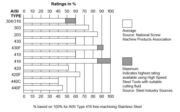
图 10(北美特种钢工业协会,第 6 页)给出了各种牌号不锈钢的可加工性(数值越高越好)。
|
|
|
空化冲蚀抗力
见此处。
粉末冶金钢
CPM® 工具钢
CPM® 指坩埚颗粒[粉末]冶金工艺(Crucible Industries),碳化钒含量在 10% 至 18% 之间。见 Haswell[1] 专利(1981 年)。
V 系列
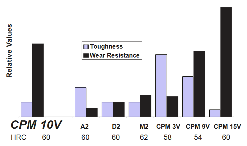
V 系列按钒含量的百分比区分。图 11 给出了性能对比。注意,性能会随 HRC 硬度而变化。不过,在指定的硬度值下,CPM 9V 和 CPM 10V 均优于 D2 和 M2。CPM 9V 似乎在韧性和耐磨性之间有最佳的折中。
|
|
|
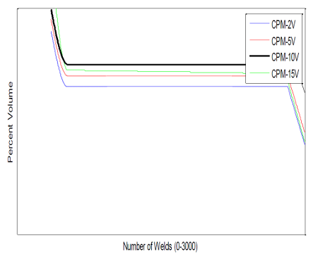
在使用 CPM 2V、5V、10V 和 15V 制变幅杆进行铜与铝试条超声焊接的试验中,Smith[1] 发现 CPM 10V 的磨损最小,同时也产生了最高的焊接强度(图 12)。(这些图所依据的原始研究似乎已无从获得。)
|
||||||||||
|
Vieira[1] 获得了一项轮胎切割变幅杆的专利,该变幅杆由粉末金属制成,钒含量在 9% 至 15% 之间(权利要求 11 和 12)。该专利预测,使用 CPM 10V 时,该变幅杆的寿命应为钛变幅杆的三倍(第 0027 段)。专利似乎暗示耐磨性的提升部分归因于钢更高的热导率,尽管这一点并不完全明确(第 0027 段)。专利称硬度应在 HRC 50-64 范围内,但不应超过 64,因为材料会变脆并容易崩缺(第 0025 和 0026 段)。专利称,与钛相比,钢制变幅杆需要"明显更高的功率"(第 0005 段)。然而,这一点未在其他地方讨论,因此尚不清楚粉末金属是否能缓解这一问题。
CPM® 9V®
特性 — 一种含 9% 钒的工具钢。它是 CPM® 10V® 的改型,降低了碳和钒含量以提高韧性,尽管其耐磨性略有降低。其可加工性是 CPM® 10V® 的两倍。
热处理 — HRC 54-56(建议用于韧性与耐磨性的最佳组合 — 见数据表)。数据表指出:"可采用更高的奥氏体化温度以获得更高的硬度,但冲击抗力会略有下降。较低的奥氏体化温度可提供最佳的冲击韧性。"数据表还指出该材料适合渗氮处理。
应用 — 焊料的超声雾化。
CPM® 10V®
特性 — 一种含 10% 钒的工具钢。它具有高耐磨性和良好的韧性。
热处理 — HRC 60(建议用于韧性与耐磨性的最佳组合 — 见数据表)。数据表指出:"可采用更高的奥氏体化温度以获得更高的硬度,但冲击抗力会略有下降。较低的奥氏体化温度可提供最佳的冲击韧性。"数据表还指出该材料适合渗氮处理。
Dukane[2](第 59 页)推荐 HRC 52–56。但 Dukane 指出:"由于 CPM10v 变幅杆的硬度较高,它们更脆;因此通常用于低振幅应用。由于脆性,变幅杆尺寸受到限制[未具体说明]。"(注 — 脆性材料在屈服点之后不会产生显著变形,粉笔就是一个例子。CPM 10V 并不符合这一定义,因此严格来说并不脆。)
"过去,Dukane 在这类应用中使用 D2 钢[见 §]。通过与冶金学家合作并经过试验,我们发现 CPM10V 更可靠。"(Dukane[2],第 59 页)可靠性的判据未具体说明,但可能是磨损、抗疲劳性或螺纹失效。(§ "严重磨损工况,如金属嵌件、焊接玻纤增强零件和切入式切割应用")
关于 30 kHz 下与 16MnCr5V 钢和 Ferro-Titanit 的对比,见 Emmer[1A]。
应用 — 超声轮胎切割(Vieira[1] 专利)、金属焊接(Lee[1],第 2 页)、金属嵌件、焊接玻纤增强零件、切入式切割。
|
||||||
|
Rex® 系列
Rex 系列含有高含量的钒、钴和钨组合。这些是用于切削刀具的高速钢。
Vieira[1] 获得了一项轮胎切割变幅杆的专利,该变幅杆由粉末金属制成,钒、钴、钨总含量在 15% 至 22% 之间(权利要求 3 和 4)。专利建议采用 Rex 45、Rex 76 和 Rex 86(第 0024 段)。最高 HRC 硬度在 65 上下。注意这些材料的可加工性相对较差(将表 8 与图 9 比较)。
|
||||||||
|
Vieira 建议的另一来源(第 0024 段)是日立金属(Hitachi Metals,其 Hap 系列)。
应用 — 超声轮胎切割(Vieira[1] 专利)、超声金属焊接(Liesegang[1A])。
Ferro-Titinat (Ferro-TiC)、CPM Rex M4、MC90 INTERMET
Liesegang[1A] 测试了由 Ferro-Titanit WFN 型、CPM Rex M4 和 MC90 钢制成的变幅杆。这些变幅杆用于 20 kHz 下 Ti-6Al-4V 的超声缝焊(图 13)。Liesegang 对这些材料的描述(第 8 页)—
- Ferro-Titanit WFN。Ferrotitanit WFN 已在商业上用作变幅杆材料。它以马氏体基体加约 33 wt% 碳化钛增强。与用作变幅杆的工具钢相比,Ferrotitanit WFN 的耐磨性似乎更高 [45]。相对较低的密度和较高的机械刚度也是其作为振动工具应用的有利性能。然而,其可加工性具有挑战性,且材料相对昂贵 [44]。
- CPM Rex M4。CPM RexM4 是一种高速工具钢,通常用于金属钻削。根据制造商数据表 [46],与商用变幅杆工具钢 CPM 10V 相比,CPM RexM4 的耐磨性较低。不过,之所以选择 Rex M4,是因为它相比其他工具钢具有较高的冲击强度 [43]。
- BÖHLER MC90 INTERMET。MC90 Intermet 是一种专为钛合金加工而开发的 FeCoMo 合金 [42]。其与钛接触时的硬度和磨损行为以及机械强度,都是其作为坚固耐用变幅杆候选材料的有利性能。
|
|
|
Liesegang 的表 5 和表 6(此处做了精简)给出了相关的材料性能。
|
||||||||||||||||||||||||||||||||
|
表注 —
- HRC = 洛氏 C 标尺硬度。
- 细杆波速为计算值。
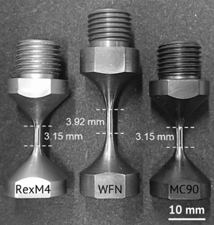
- Ferro-Titanit 的细杆波速比另外两种钢高约 30%。这意味着变幅杆的调谐长度将相应更长。图 14 中的 20 kHz 疲劳试样说明了这一点(见图 14)。(注意,由于波节中部截面的面积极度缩减,所有长度都相当短。)
- 疲劳强度(图 15)取自 2.5e9 次循环处出现未失效试样(run-out)的位置。然而数据有限,真实疲劳强度可能有所不同。
- 试样直径较小。大型谐振器存在材料缺陷的可能性更大,因此真实疲劳强度可能更低。见 Ferro-Titanit WFN。
- 疲劳应变为计算值。
|
|
|
|
|
|
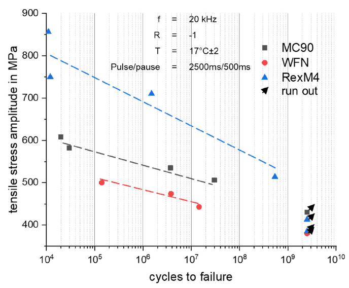
注意,表 9 中的疲劳应变均显著低于 Ti-6Al-4V 的最大推荐应变(约 0.0032)。因此,如果需要高应变(高振幅),可以考虑使用带耐磨涂层的 Ti-6Al-4V。
除非另有说明,以下焊接结果均来自 Liesegang[1A]。
焊接结果 — MC90
在三种受试材料中,MC90 获得了最好的焊接强度(第 14 页)。Liesegang(第 15 页)指出 —
"与商业上应用的变幅杆材料相比,MC90 的性能非常出色。在 Ti6Al4V 与 CFRP 的焊接中,以超过 48 m 的位移振幅进行了超过 108 次加载循环,未发生失效且无明显磨损 [14]。该变幅杆累计焊接缝长度达 40 m,约相当于 3 x 10⁸ 次加载循环。在本研究中,未检测到接头[焊缝]质量随工具寿命推移而持续下降。"
尽管 MC90 在钛的超声焊接中表现良好,Bloss[1] 发现焊接性能受变幅杆端头与工件之间材料相容性的影响。因此,尚不清楚 MC90 在焊接其他材料时会有怎样的表现。
焊接结果 — CPM Rex M4
由于端头磨损非常严重,焊接强度"异常低"(第 14 页)。"在累计焊接缝长度达到 1 m 后,RexM4 变幅杆端头轮廓的高度减少了约 30%,而 WFN 和 MC90 的变幅杆端头未出现明显磨损。"
焊接结果 — Ferro-Titinat WFN
Ferro-Titinat WFN 变幅杆在焊接过程中因疲劳而失效。疲劳发生的部分原因是 Ferro-Titinat 的杨氏模量高于其他材料,导致在相同振幅下应力高出 13%(Liesegang 的图 11)。Liesegang 还认为疲劳失效可能源于 TiC 团簇处的"机械应力增强"(疲劳裂纹萌生的位置)。基于这些失效,Liesegang 认为 350 MPa 的疲劳强度假定值可能过高(第 15 页)。然而,在疲劳失效之前,Ferro-Titinat WFN 的焊接强度与 MC90 相当(第 15 页)。因此,Liesegang 建议,如果能重新设计变幅杆以降低应力,Ferro-Titinat WFN 或许是合适的(第 16 页)。
Ferro-Titinat 的性能见 Foller[1A]。注 —
- Ferro-Titinat 有多个牌号,各牌号的性能略有不同。
- Foller 的波速(其表 2)由超声脉冲回波技术测定。这些是膨胀波速。它们高于细杆波速,不应用于设计目的。不过,Foller 表 2 中的其他材料性能是有效的。
热处理
除上文特别推荐外,常规热处理建议(未考虑超声要求)见 Bryson[1]。可咨询材料制造商或您的热处理厂商,他们可能有更多建议。
对频率的影响
钢谐振器经热处理后,其谐振频率往往会发生变化。在热处理之前进行调谐时必须考虑这一点,以保证最终频率正确。
Liesegang[1A](第 13 页)报告了以下结果 —
|
||||||||||||
|
Liesegang 指出,Ferro-Titanit WFN 含 33%(重量比)的陶瓷相,该相不受热处理影响;因此,与另外两种材料相比,Ferro-Titanit WFN 的频率下降较小。
Culp[0] 报告称 D2 工具钢热处理后频率下降约 200 Hz。
Steel properties
Contents
- Figures
- Figure 1. Steel metal welding horn with integral welding surface
- Figure 2. Shock resistance comparison chart
- Figure 3. Power loss of acoustic materials at 15 kHz
- Figure 4. Test setup to measure loss (Aeroprojects)
- Figure 5. Effect of grain size on internal friction Q-1
- Figure 6. Composition and treatment of test steels
- Figure 7. Effect of temperature on modulus of elasticity for various steels
- Figure 8. Effect of temperature on modulus of elasticity for various structural steels
- Figure 9. Tool steel machinability rating relative to W1 steel
- Figure 10. Comparative machinability of frequently used stainless steels and their free-machining counterparts
- Figure 11. Comparative toughness and wear resistance of CPM® steels
- Figure 12. Metal welding tests with CPM® horns
- Figure 13. 20 kHz rotary metal welding horn
- Figure 14. 20 kHz fatigue test specimens
- Figure 15. Ferro-Titinat WFN, CPM Rex M4, MC90 — 20 kHz fatigue test results
- Tables
- Table 1. Materials in figure 3
- Table 2. Details of figure 6
- Table 3. Effect of temperature on modulus of elasticity for various steels
- Table 4. Curve fit parameters for equation \eqref{eq:15301a}
- Table 5. Material properties of various steels
- Table 6. Loss measurements for various stainless steels
- Table 7. Machinability of CPM® V® materials
- Table 8. Machinability of CPM® Rex® materials
- Table 9. Properties of Ferro-Titanit WFN compared Rex M4 and MC90
Steels are used for ultrasonic resonators when wear resistance and/or impact resistance are required. For example, they have been used for metal welding horns (where the welding tip surface is integral to the horn — figure 1) and for horns that are used for insertion.
|
|
|
Material selection
Unlike titanium and aluminum, selecting an appropriate steel is complicated by several factors.
- There are thousands of different steels. Some have just slightly different alloy compositions but with big impact on performance.
- For heat-treatable steels there are many heat-treat variables that affect performance, for example the temperatures and durations (for preheating, heat treating, quenching, tempering), the surrounding media (air, inert gas, salts), etc. These may vary even for a specific steel, depending on the desired final properties.
- Although steels work well at relatively low strains, the loss can increase dramatically at higher strains (see figure 3 and table 1). Conventional (handbook) property listings don't specify loss properties because —
1) Loss isn't important for conventional (non-ultrasonic) applications.
2) Loss is not a fixed value but varies with the strain.
3) Loss depends on the heat treatment.
Instead, loss must be determined by actual ultrasonic tests at the expected strain levels for each material and heat treatment. Although low loss is important, other desired properties such as wear and notch sensitivity (e.g., for threads) must also be considered.
Fatigue
See a general discussion of fatigue. In addition, the following are specific to steel.
Notch sensitivity
A desirable property of acoustic materials is that they should have low fatigue notch sensitivity (i.e., the endurance strength with a notch should be be nearly equal to the same material without a notch). This is important, for example, in fatigue of threads.
Two similar tests that determine impact notch sensitivity are the Charpy and Izod. In these tests a heavy pendulum strikes and breaks a notched test specimen. The change in potential energy of the pendulum (before and after the strike) indicates the impact notch sensitivity. Figure 2 shows the impact shock resistance of various steels based on Charpy "V" notch test results. (Bryson[1], p. 139) Note — the vertical blue line has been added. It represents the Charpy "V" notch results for Ti-6Al-4V (annealed and STA sheet and bar). (See TIMET[1], figure 26, p. 18.) (Because titanium is orthotropic, its shock resistance depends on the test direction.)
|
|
|
Unfortunately, there may be little correlation between the impact notch sensitivity and fatigue notch sensitivity. As Yen[1] (p. 12) relates, "It is generally believed that hard steels are more notch-sensitive than soft steels either in a fatigue test, a static tension test, or an impact test. Some test data have indicated that the stronger the steel the lower is the Charpy impact value and the greater the fatigue notch-sensitivity; hence, one might infer the possibility of a relation between impact values and fatigue notch-sensitivity. However, no direct correlation between these two types of test has ever been reported and some contrary evidence indicating that there is no reason to expect a correlation has been presented".
Threads
Steel horns are known to fail in the threads.
Loss
Figure 3 shows the loss for a number of materials, including several steels. (This data, from Aeroprojects 1969, was conveyed to Culp[0] by Maropis[0].) The experimental setup is shown in figure 4. The loss was determined from the increase in temperature of water that flowed through the center of a highly stressed 15 kHz horn. Note that the losses are only valid for the particular frequency and sample shape. However, comparisons among the various materials are still valid. Table 1 shows the best determination of the hand-written notes from figure 3.
Notes —
- All steels are more lossy than Ti-6Al-4V and many are substantially more lossy.
- For 440-C steel, the wave speed decreases from 5350 m/sec to 5200 m/sec (-2.8%) as its condition changes from annealed to full hard. D2 exhibits a similar trend.
|
|
|
|
|||||||||||||||||||||||||||||||||||||||||||||||||||
|
|
|
|
Also see Loss measurements in stainless steel.
Effect of grain size
Puskar[1] tested a low carbon unalloyed steel at 23 kHz to determine the internal friction Q-1. (Note — loss varies directly with the internal friction which is the reciprocal of the quality factor Q.) The results are shown in figure 5 where the horizontal axis is the total strain amplitude \( \epsilon_{at} \). (It is believed that this is the peak strain rather than the peak-to-peak strain although this is not explicitly stated.)
As the grain size is reduced (likely due to the heat treatment process) the internal friction is also reduced. It is likely that there is some point at which further reduction in grain size does not result in further reduction in internal friction. However, this cannot be deduced from the given data.
Figure 5 also shows that, up to a certain critical strain \( \epsilon_{c} \), the internal friction Q-1 remains constant. Above this critical strain the internal friction begins to increase (i.e., the internal loss increases faster than the stored energy). It is desirable that \( \epsilon_{c} \) should be as large as possible so that a resonator can be vibrated at high amplitude without experiencing unexectedly high loss. Figure 5 shows that \( \epsilon_{c} \) is largest when the grain size is smallest. For example, for a grain size of 0.620 mm \( \epsilon_{c} \) is 7.3e-5 whereas for a grain size of 0.022 mm \( \epsilon_{c} \) increases to 1.3e-4.
Also, there is a critical strain \( \epsilon_{c} \) at which the internal friction starts to increase (i.e., the curves trend upward). This critical strain is the strain at which the internal loss increases faster than the stored energy.
\( \epsilon_{c} \) increases as the grain size decreases. For example, for a grain size of 0.620 mm \( \epsilon_{c} \) is 7.3e-5 whereas for a grain size of 0.022 mm \( \epsilon_{c} \) increases to 1.3e-4. Thus, considering only the effect of loss, this fine-grained material could be driven at substantially higher amplitudes than the same coarse-grained material. The same is likely true for other steels.
|
|
|
Temperature effects
Effect on modulus of elasticity (Young's modulus)
The modulus of elasticity of steel decreases with increasing temperature (i.e., the material is easier to compress). Thus, resonators that operate at elevated temperatures must have a shorter tuned length in order to maintain a compatible operating frequency.
Particular steels
Garofalo[1] tested a series of steels to determine the relation between modulus of elasticity and temperature. Figure 6 shows the specifics of those steels.
|
|
|
|
||||||||||||||||||||
|
Figure 7 (Garofalo[1], p. 18) shows the results of Garofalo's tests together with test results from other sources.
|
|
|
Results (pp. 19-20) —
|
||||||||||||||||||
|
Note from figure 7 that the trends for many of the materials become nonlinear above about 900 °F (480 °C). The 300 series stainless steels often remain reasonably linear up to 1200 °F (650 °C) or higher.
Generic structural steels
Figure 8 (Seif[1], p. 9) shows the relation between modulus of elasticity and temperature for various "structural" steels from various testing sources (data sets). (See Seif[1] (p. 13) for more information.) Equation \eqref{eq:15301a} gives the associated least-squares regression curve fit, based on temperature data up to 725 °C.
Note the large data scatter in figure 8. Thus, figure 8 and equation \eqref{eq:15301a} should only be used if specific temperature data for the desired material are not otherwise available.
|
|
|
Figure notes —
- \( T \) is in °C.
- \( E_{20} \) is the modulus at 20 °C.
Regression equation for the curve of figure 8 —
\begin{align} \label{eq:15301a} \frac{E(T)}{E_{20}} &= \textsf{exp} \left\{ -\small\frac{1}{2} \left(\frac{T-20}{C_3}\right)^{C_1} \, -\small\frac{1}{2} \left(\frac{T-20}{C_4}\right)^{C_2} \right\} \end{align}
Equation notes —
- \( T \) is in °C.
- The equation constants are given in table 4. (See Seif[1], table 5‑2 (last four rows), p. 19. Note that fit constant \(C_2\) was forced to unity and was not fit (p. 11)).
Tabl 4. Curve fit parameters for equation \eqref{eq:15301a} Parameter Units Value \(C_1\) ——— 3.768 \(C_2\) ——— 1.000 \(C_3\) °C 639 \(C_4\) °C 1650
Effect on Poisson's ratio
Machinability
Figure 9 shows the machinability of various steels relative to W1 (a water hardening steel) at 100, where the machinability of W1 equals 40% on the AISI B1112 scale. (Bryson[1], p. 141. Note — the vertical blue line has been added. It represents the machinability of Ti-6Al-4V which is 22% on the AISI B1112 scale (Carpenter[1], p. 6) or 55% relative to W1.) Also see figure 10 for machinability of various stainless steels.
|
|
|
Known steels
The following steels have been used in some manner for ultrasonic resonators. The comparative merits of these steels are only partially known.
|
|||||||||||||||||||||||||||||||||||||||||||||||||||||||||||||||||||||||||||||||||||||||||||||||||||||||||
|
Table notes —
- HRC = hardness on the Rockwell C scale.
- The thin-wire wave speeds are calculated values.
- Bold type — Data that are measured or calculated from ultrasonic tests. Except as noted, these are from Culp[0]. Corresponding nominal "handbook" data (typically from manufacturer's data or matweb.com) are in parentheses.
- Unless otherwise stated, all properties are at room temperature.
Table references —
- FX Temper 2 tool steel —
Poisson's ratio was measured with tensile tests on three samples (25.4 mm square).
The density was measured in the laboratory.
- Young's modulus was measured with a 40 kHz ultrasonic full-wave/half-wave test (one sample). The test sample was Ø19.1 mm.
- Young's modulus was calibrated from FEA of a 40 kHz 2-slot bar horn (one sample each).
- Young's modulus was calibrated from FEA of a 40 kHz unslotted flatted-cylindrical horn.
- Al-Sarrif[1] — 20.8 kHz metal welding horn (FEA calibrated); 20 microns p-p (p. 68); 5 microns p-p input. The integrated welding tip was hardened to HRC 55-60 (p. 54); it is not known if this hardness applied only to the welding tip or to the entire horn.
- Stanasel[1] — 20 kHz metal welding horn (figure 1) for welding cables for the automotive industry, FEA analysis. Stanasel gives partial horn dimensions.
Notes for the following materials —
- Except as specifically recommended below, see Bryson[1] for suggested conventional heat treatments (without consideration of ultrasonic requirements). Consult the material manufacturer or your heat treater who may have additional recommendations.
- Unless otherwise stated, the "Characteristics" below are from the manufacturer's data or, alternately, from matweb.com.
- The listed applications are those which are known or available through the literature. The listed applications are not comprehensive and in many cases a particular material could easily be used for multiple applications. Also, some applications may be for prototype development where the chosen material may have been a matter of convenience, rather than an attempt for an optimal material.
Tool steels
AISI A2 tool steel
Characteristics — "High hardenability, high degree of dimensional stability in heat treatment, good wear resistance, fatigue life, toughness, and deep hardening qualities."
Applications — Ultrasonic processing of petroleum products. See Gunnerman's patent[2], paragraph 0013. (Note — The patent specifies "2‑A tooling steel". However, no such material could be identified. From the specified composition (paragraph 0013) the material is likely A2.)
AISI D2 tool steel
Characteristics — An air-hardening, high carbon, high chromium tool steel, heat treatable to HRC 60-62. It has excellent abrasion resistance due to a large volume of carbides in the microstructure.
Applications — Ultrasonic metal welding tips, plastics sealing horns, inserting horns.
AISI M2 tool steel
Characteristics — A tungsten-molybdenum high speed tool steel with excellent combination of wear resistance, toughness and hot hardness.
Applications — Ultrasonic metal welding horns and tips.
Suggested heat treatment for HRC 61-62 —
- With the part in the oven, preheat the oven in three steps for stress relieving.
- 620 °C (1150 °F) for 30 minutes
- 840 °C (1550 °F) for 15 minutes
- 1040 °C (1900 °F) for 15 minutes
- Hardening temperature — 1120-1180 °C (2050-2150 °F)
- Vacuum quench
- Double temper at 540-590 °C (1000-1100 °F). This will not reduce the hardness.
Vertex
Characteristics — "TLS Vertex tool steel is a versatile, high-chromium, air-hardening tool steel that is characterized by a relatively high attainable hardness and numerous, chromium-rich alloy carbides in the microstructure. These carbides provide good resistance to wear from sliding contact with other metals and abrasive materials. The primary alloy carbides in Vertex are smaller than the large chromium-rich alloy carbides which are characteristic of D2 tool steel. These smaller carbides result in better impact toughness and superior fatigue properties compared to D2.
The molybdenum addition in Vertex enhances the hardness of the alloy carbides, and more significantly, provides superior secondary hardening response compared to D2. Therefore, unlike D2, Vertex can be tempered at higher tempering temperatures yet still attain a hardness in excess of 60 Rockwell C. Because of the higher secondary hardness, Vertex exhibits superior wear resistance compared to D2 tempered at the higher tempering temperatures, as well as the superior toughness that is the result of the high-temperature tempering." (Vertex data sheet)
Originally manufactured by Timken Latrobe Steel; now Latrobe Specialty Steels Co.
Heat treatment (suggested by Latrobe). Final hardness should be ~HRC 56.
- Preheating. Preheat at a rate not exceeding 400 °F/hr (220 °C/hr) to 1150 - 1250 °F (621 -677 °C), equalize, then heat to 1400 - 1450 °F (760 - 788 °C).
- Austenitizing. Heat slowly from preheat. Furnace or Salt: austenitize at 1850 °F (1010 °C)
- Quenching. Air or pressurized gas. Cool to 150 - 125 °F (66 - 51 °C).
- Tempering. Temper immediately after quenching. Heat to 1050 °F (565 °C). Hold at temperature for 1 hour per inch of thickness (2 hours minimum), then air cool to ambient temperature and repeat.
FX Temper 2
Characteristics — "A moderate level of alloys nickel (Ni .80%), chromium (Cr 1.15%) and molybdenum (Mo .5%) provides this die steel with a good balance between fracture toughness and wear resistance at the widely used Temper 2 hardness (38-42 HRC)."
Manufactured by Finkl Steel. See data sheet.
Applications — Ultrasonic atomization of solder (Culp[0]).
Stainless steels
AISI 630 (17Cr-4Ni; 17-4 PH) stainless steel
PH refers to precipitation hardening.
Characteristics — A martensitic precipitation/age-hardening stainless steel offering high strength and hardness along with excellent corrosion resistance.
Applications — Ultrasonic dental tips.
AISI 304 stainless steel
Characteristics — Better corrosion resistance than Type 302. Resists most oxidizing acids and salt spray.
Applications — Sonochemistry.
Loss measurements
Table 6 shows loss measurements for several stainless steel materials (Culp[0]). Ony a single sample of each material was tested. Note that the loss for the 4xx series is significantly higher than the 3xx series even though the 4xx series has higher hardness (which is typically associated with lower loss). Also note that the 4xx series has no nickel content; it is not known if this contributes to its relatively high loss.
|
||||||||||||||||||||||||||||||||||||||||||
|
Table notes —
- Materials —
Only the most significant chemical components are listed. Other components may include manganese, molybdenum, phosphorous, silicon, and sulfur.
Inspection certificates with hardness values were provided.
Approximate equivalent HRC hardnesses are shown in ( ).
Ti-6Al-4V data are provided for comparison. - Horn dimensions —
Output diameter = 17.5 mm
Input diameter = 38.1 mm
Rear shoulder length = 25.4 mm
Transition radius = 38.1 mm
3/8-24 step stud (unbottomed) - Test equipment —
Frequencies — Branson A200A (low amplitudes)
Amplitudes —Fotonic Sensor
Power — Clarke-Hess watt meter (the loss includes that of the driving transducer)
Power supply — Sonics & Materials 600 watt Vibracell set at 40%
Transducer — same for all tests
Machinability
Figure 10 (Speciality Steel Industry of North America, p. 6) shows the machinability for various grades of stainless steel (higher values are better).
|
|
|
Cavitation erosion resistance
See here.
Powder metallurgy steels
CPM® tool steel
CPM® refers to the Crucible Particle [powder] Metallurgy process (Crucible Industries) with vanadium carbide between 10% and 18%. See Haswell[1] patent (1981).
V series
The V series differentiates based on the vanadium percent content. Figure 11 shows comparative performance. Note that the performance will change depending on the HRC hardness. However, for the specified hardness values both CPM 9V and CPM 10V are superior to D2 and M2. CPM 9V seems to have the best compromise of toughness and wear resistance.
|
|
|
In ultrasonic welding of copper to aluminum test strips using horns made of CPM 2V, 5V, 10Vand 15V, Smith[1] found that CPM 10V had the least wear and also produced the highest weld strengths (figure 12). (The original research for these graphs does not seem to be available.)
|
||||||||||
|
Vieira[1] has patented a tire cutting horn that is made from powdered metal with a vanadium content between 9% and 15% (claims 11 and 12). Using CPM 10V the patent predicts that this horn should last three times longer than a titanium horn (paragraph 0027). The patent seems to suggest that the wear is improved, in part, by the higher thermal conductivity of the steel, although this is not entirely clear (paragraph 0027). The patent says that the hardness should be in the range of HRC 50-64 but should not exceed 64 because the material becomes brittle and tends to chip (paragraphs 0025 and 0026). The patent says that steel horns draw "meaningfully higher power" compared to titanium (paragraph 0005). However, this is not addressed elsewhere so it is not known if the powdered metal reduces this problem.
CPM® 9V®
Characteristics — A tool steel with 9% vanadium. It is a modification of CPM® 10V® with lower carbon and vanadium to improve toughness, although its wear resistance is somewhat lower. Its machinability is twice as good as CPM® 10V®.
Heat treatment — HRC 54-56 (suggested for best combination of toughness and wear resistance — see the data sheet). The data sheet notes, "Higher austenitizing temperatures can be used to obtain higher hardness, at a slight decrease in impact resistance. The lower austenitizing temperatures provide the best impact toughness." The data sheet also indicates that this material is suitable for nitriding.
Applications — Ultrasonic atomization of solder.
CPM® 10V®
Characteristics — A tool steel with 10% vanadium. It has high wear resistance and good toughness.
Heat treatment — HRC 60 (suggested for best combination of toughness and wear resistance — see data sheet). The data sheet notes, "Higher austenitizing temperatures can be used to obtain higher hardness, at a slight decrease in impact resistance. The lower austenitizing temperatures provide the best impact toughness." The data sheet also indicates that this material is suitable for nitriding.
Dukane[2] (p. 59) recommends HRC 52–56. However, Dukane notes, "Due to the hardness of the CPM10v horns, this causes them to be more brittle; thus, they are usually used for low amplitude applications. There are horn size limitations [unspecified] due to the brittleness." (Note — A brittle material does not have significant deformation beyond its yield point; chalk is an example. CPM 10V does not fit this definition and so is technically not brittle.)
"In the past, Dukane used D2 steel for this type of application [see §]. Working with metallurgists and through experimentation, we discovered CPM10V to be more reliable." (Dukane[2], p. 59) The criteria for reliability are not specified but may possibly be wear, fatigue resistance, or failure in the threads. (§ "severe wear, such as metal insertion, welding glass filled parts, and plunge cutting applications")
See Emmer[1A] for comparisons to 16MnCr5V steel and Ferro-Titanit at 30 kHz.
Applications — Ultrasonic tire cutting (Vieira[1] patent), metal welding (Lee[1], p. 2), metal insertion, welding glass filled parts, plunge cutting.
|
||||||
|
Rex® series
The Rex series has a high combination of vanadium, cobalt, and tungsten. These are high speed steels that are used in cutting tools.
Vieira[1] has patented a tire cutting horn that is made from powdered metal with combined vanadium, cobalt, and tungsten between 15% and 22% (claims 3 and 4). The patent suggests Rex 45, Rex 76, and Rex 86 (paragraph 0024). Maximum HRC hardnesses are mid-to-upper 60's. Note the relatively poor machinability of these materials (compare table 8 to figure 9).
|
||||||||
|
Another source suggested by Vieira (paragraph 0024) is Hitachi Metals (their Hap series).
Applications — Ultrasonic tire cutting (Vieira[1] patent), ultrasonic metal welding (Liesegang[1A]).
Ferro-Titinat (Ferro-TiC), CPM Rex M4, MC90 INTERMET
Liesegang[1A] tested the horns made of Ferro-Titanit type WFN, CPM Rex M4, and MC90 steels. These were used for ultrasonic seam welding of Ti-6Al-4V at 20 kHz (figure 13). Liesegang described these materials (p.8) —
- Ferro-Titanit WFN. Ferrotitanit WFN is already used commercially as a sonotrode material. It offers a martensitic matrix reinforced by approximately 33 wt% titanium carbide. In comparison to tool steels used for sonotrodes, the wear resistance of Ferrotitanit WFN seems to be higher [45]. Relatively low mass density and high mechanical stiffness are also promising properties for applications as an oscillating tool. However, its machinability is challenging and the material is comparatively expensive [44].
- CPM Rex M4. CPM RexM4 is a high-speed tool steel, typically used metal drilling. Compared to the commercially used sonotrode tool steel CPM 10V, the wear resistance of CPM RexM4 is lower, according to the manufacturer?s data sheet [46]. However, Rex M4 was selected because of its high impact strength in comparison to other tool steels [43].
- BÖHLER MC90 INTERMET. MC90 Intermet is a FeCoMo-alloy developed particularly for the machining of titanium alloys [42]. Hardness and wear behaviour in contact with titanium, as well as mechanical strength, are promising properties as a candidate for robust sonotrodes.
|
|
|
Liesegang's tables 5 and 6 (condensed here) show the relevant material properties.
|
||||||||||||||||||||||||||||||||
|
Table notes —
- HRC = hardness on the Rockwell C scale.
- The thin-wire wave speeds are calculated values.
- Ferro-Titanit's thin-wire wave speed is about 30% higher than the other two steels. This means that a horn's tuned length will be correspondingly longer. This is illustrated in figure 14 for the 20 kHz fatigue test specimens. (Note that all of the lengths are quite short due to the extreme area reductions at the nodal midsections.)
- The fatigue strengths (figure 15) are taken at 2.5e9 cycles where run-outs have occurred. However, the data are limited so the true fatigue strengths may differ.
- The diameters of the test specimens are small. Large resonators may have greater possibilities for material defects so the true fatigue strengths may be lower. See Ferro-Titanit WFN.
- Fatigue strains are calculated values.
|
|
|
|
|
|
Note that the fatigue strains of table 9 are all significantly lower than the maximum recommended strain for Ti-6Al-4V (~0.0032). Thus, if high strains (amplitudes) are required then Ti-6Al-4V with a wear coating might be considered.
Unless otherwise noted, the following welding results are from Liesegang[1A].
Welding results — MC90
Of the three tested materials, MC90 achieved the best weld strengths (p. 14). Liesegang (p. 15) notes —
"In comparison to commercially applied sonotrode materials, the performance of MC90 is outstanding. Displacement amplitudes above 48 m were applied for more than 108 loading cycles during the welding of Ti6Al4V to CFRP without failure and without pronounced wear [14]. The sonotrode was used for a cumulative welding seam length of 40 m corresponding to approximately 3 x 10⁸ loading cycles. A continuous decrease in joint [weld] quality over tool's longevity was not detected during the study."
Although MC90 performed well for ultrasonic welding of titanium, Bloss[1] found that welding performance is affected by material compatibility between the horn-tip and the workpiece. Thus, it is not known how MC90 would fare when welding other materials.
Welding results — CPM Rex M4
The weld strengths were "exceptionally low" due to very pronounced tip wear (p. 14). "After a cumulated welding seam length of 1 m, the height of the RexM4 sonotrode tip profile was reduced by approximately 30%, whereas the sonotrode tips of WFN and MC90 did not show significant abrasion."
Welding results — Ferro-Titinat WFN
Ferro-Titinat WFN horns failed by fatigue during welding. Fatigue occurred, in part, because the Ferro-Titinat has higher Young's modulus than the other materials, resulting in 13% higher stress for the same amplitude (Liesegang's figure 11). Liesegang also suggests that the fatigue failures may have been due to "enhanced mechanical stress" at the TiC clusters (the sites of fatigue crack initiation). Based on these failures Liesegang assumed fatigue strength of 350 MPa was probably too high (p. 15). However, until the fatigue failures, Ferro-Titinat WFN gave similar weld strengths to MC90 (p. 15). Thus, Liesegang suggested that Ferro-Titinat WFN might be suitable if the horn could be redesigned for reduced stress (p. 16).
See Foller[1A] for Ferro-Titinat properties. Note —
- There are several grades of Ferro-Titinat, each of which has slightly different properties.
- Foller's wave speeds (his table 2) were determined the the ultrasonic pulse-echo technique. These are the dilatational wave speeds. These are higher than the thin-wire wave speeds and should not be used for design purposes. However, the other material properties in Foller's table 2 are valid.
Heat treatment
Except as specifically recommended above, see Bryson[1] for suggested conventional heat treatments (without consideration of ultrasonic requirements). Consult the material manufacturer or your heat treater who may have additional recommendations.
Effect on frequency
When a steel resonator is heat treated, its resonant frequency often changes. This must be considered when tuning prior to heat treatment so that the final frequency is correct.
Liesegang[1A] (p. 13) reported the following —
|
||||||||||||
|
Liesegang noted that Ferro-Titanit WFN is 33% (by weight) ceramic phase which is unaffected by heat treatment; hence, Ferro-Titanit WFN has a smaller frequency drop compared to the two other materials.
Culp[0] reports approximately 200 Hz frequency drop after heat treating D2 tool steel.