振幅均匀性 — 基本概念
本节将讨论振幅均匀性的一些一般性问题。
定义
振幅均匀性(一般简称 "均匀性")是衡量振幅在给定表面上变化程度的量。
对均匀变幅杆的需求
考虑一个超声塑料焊接应用,其中要把两条非常柔软、厚度均匀的条带焊接在一起。为使焊缝沿整个接头均匀,必须向焊接接头的每一点输送等量的超声能量。由于能量输送是变幅杆振幅的函数,等量能量输送要求变幅杆在与条带接触的每个位置都具有相等的振幅。如果变幅杆端面振幅不均匀,那么接头的某些区段可能焊接不足,而其他区段则焊接过度。因此,变幅杆端面振幅的均匀性是变幅杆设计中的一个重要考虑因素。(注:目前本讨论仅限于变幅杆端面的均匀性。不过,螺柱表面上的振幅均匀性同样重要,后文将予以讨论。)
具体的均匀性要求取决于应用。刚性塑料对不均匀的变幅杆有一定的容忍度。这是因为硬质塑料能把超声能量传递到相邻的接头区域,从而使沿接头的能量分布更加均匀。此外,刚性塑料允许采用(导能筋)接头形式,有时可以弥补变幅杆均匀性的不足。最后,许多塑料焊接应用只要求一定的平均焊接强度,因此沿接头存在一定程度的过焊和欠焊是允许的。
在某些情况下需要高均匀性:
- 密封焊(气密封接)。密封焊要求沿其整个周长都具有足够的接头强度。均匀的变幅杆可以提高成功的概率。
- 薄膜应用。焊接薄膜(如合成纤维织物)时,薄膜太柔软,无法把超声能量传递到相邻区域。而且薄膜无法设计导能筋。因此,获得良好焊接的全部责任都落在变幅杆身上(假定夹具已正确设计)。
- 组合变幅杆。组合变幅杆由一个母变幅杆和安装在其上的子变幅杆组成。如果母变幅杆的端面振幅不均匀,子变幅杆就会发生弯曲。这可能导致子变幅杆的疲劳失效、子变幅杆与母变幅杆之间的接头问题、换能器的弯曲失效、寄生谐振问题以及焊接不良。
- 高振幅接头。当接头在高振幅下工作时,接触界面处的微动磨损可能使接头恶化。这会导致发热和更大的功率损耗;问题严重时接头可能咬死。如果接头振幅高且变幅杆沿接头的均匀性差,这个问题会更加严重。
不均匀性的成因
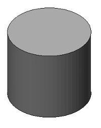
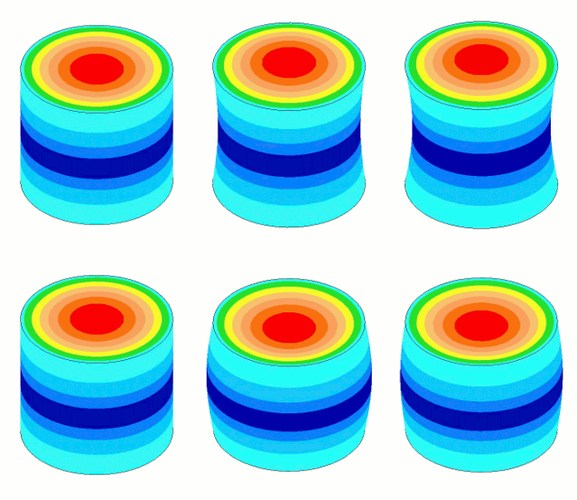
振幅不均匀性是由泊松耦合引起的,因此谐振器在纵向振动的同时会沿横向 "呼吸"。然而,这种呼吸沿谐振器长度方向并不均匀 — 即呼吸量在应变(应力)最大处最大。因此,对于无外形谐振器,呼吸量在波节处最大,在输出端面和输入端面处最小(接近于零)。这种不均匀的呼吸分布导致端面振幅不均匀。该效应如图 1 所示。
|
|||||||||||||||
|
呼吸量取决于三个因素。
- 泊松比。泊松比高的材料呼吸更明显,因此振幅均匀性更差。
- 细杆波长。波长短(波速低)的材料在给定振幅下应变更大,因此呼吸也更明显。
- 横向尺寸。宽度、厚度或直径大的谐振器比细长的同类谐振器呼吸更明显。
第一个因素仅取决于材料。第二个因素取决于材料(波速)和频率。第三个因素取决于谐振器设计。第二和第三个因素可以结合起来定义谐振器的细长比。
\begin{align} \label{eq:10201a} \textsf{Slenderness} = \frac{\textsf{Lateral dimension}}{\textsf{Thin-wire half wavelength}} \end{align}
对于无外形谐振器,横向尺寸就是直径。因此,当谐振器直径等于细杆半波长时,细长比为 1.0。
注意,波长与频率成反比。因此,如果谐振器的横向尺寸不变,在 20 kHz 下显得细长的谐振器在 40 kHz 下可能显得 "粗短"。(并没有一个具体的细长比值可以用来判定谐振器为粗短。)
因此,为减少呼吸并改善均匀性 —
- 谐振器应当细长(波长长且横向尺寸小)。
- 谐振器材料应具有较低的泊松比。
下面的表和图展示了由典型声学材料(铝、钛和钢)以及两种相当极端的材料(AlBeMet® 162 和黄铜)制成的 20 kHz 无外形 Ø125 mm 变幅杆的这些效应。
|
||||||||||||||||||||||||||||||||||||||||||
|
表注:
- 该变幅杆无外形,且不带螺柱。
- 下表给出了上表的一些补充信息。注意,铝、钛和钢均采用通用材料性能参数。
表 2. 表 1 的补充信息 材料 杨氏模量
(GPa)密度
(kg/m3 )20 kHz 时的调谐长度
(mm)AlBeMet® 162 193 2100 238 铝 74 2840 112 钛 119 4430 115 钢(工具钢) 208 7670 119 黄铜 (C26000) 110 8525 38 - 细杆波速按 \( \sqrt{\textsf{Young's modulus}/{\textsf{Density}}} \) 计算。
- 给出的调谐长度仅适用于 20 kHz 无外形 Ø125 mm 变幅杆。
- 参见均匀性计算公式。
- 最大径向振幅出现在波节处。其数值是相对于变幅杆端面中心轴向振幅的值。
|
|
|
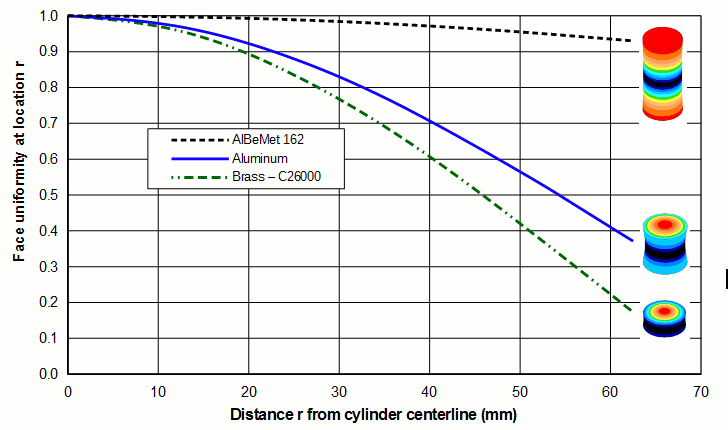
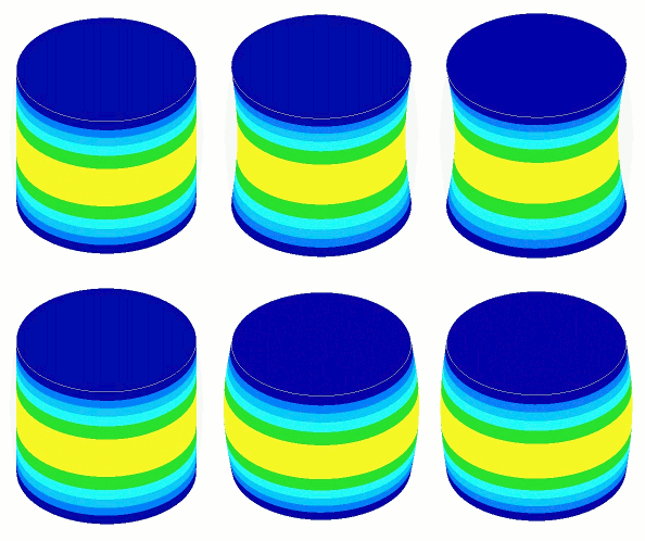
上图中的轴向振幅图像在下文图 3 中放大显示。均匀性最好的变幅杆是端面上振幅环纹最少的那个。(沿长度方向的环纹数量并不重要。)在本例中,AlBeMet® 明显最优。
|
|||||||||||||||
|
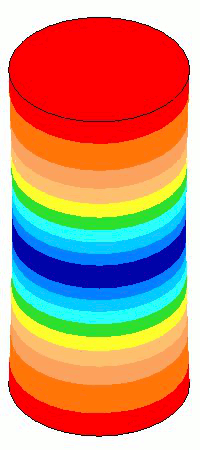
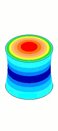
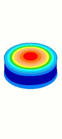
从均匀性角度来看,AlBeMet® 162(62% 铝、38% 铍)具有非常理想的性能——波速高,使其相对于直径而言长度较长,且泊松比低;其均匀性达到 0.93。另一方面,黄铜的性能相当不理想——波速低,使其相对于直径而言长度较短,且泊松比高;其均匀性仅为 0.17。事实上,在这个直径下,黄铜的表现更像一个径向振动的圆盘而不是轴向谐振器,因为其径向振幅比轴向振幅大 47%。
(尽管 AlBeMet® 162 表现出优异的均匀性,但由于其含铍,它至少有两个重大问题:1)价格非常昂贵;2)如果在加工过程中吸入任何铍粉尘,会造成健康危害。)
由于波速和泊松比相近,铝、钛和钢的轴向均匀性和径向振幅大体相似(但并不完全相同)。
其他谐振器类型
尽管上述讨论是针对无槽圆柱形变幅杆的,但同样的原理也适用于其他谐振器类型(开槽圆柱形变幅杆、条形变幅杆和块形变幅杆)。改善均匀性的方法将在别处讨论。
Amplitude uniformity — basic concepts
Contents
- Definition
- Need for uniform horns
- Cause of nonuniformity
- Also see — Uniformity and asymmetry calculations
- Figures
This section will consider some general aspects of amplitude uniformity.
Definition
Amplitude uniformity (generally just "uniformity") is a measure of how much the amplitude varies over a given surface.
Need for uniform horns
Consider an ultrasonic plastic welding application in which two very compliant strips of uniform thickness are to be welded together. To get uniform welding along the joint, an equal amount of ultrasonic energy must be delivered to each point along the weld joint. Since energy delivery is a function of the horn amplitude, equal energy delivery requires equal horn amplitude at each location where the horn contacts the strip. If the horn face amplitude is not uniform, then some section of the joint may be underwelded while other sections are overwelded. Thus, the uniformity of horn face amplitude is an important consideration in horn design. (Note: for the present this discussion will be confined to horn face uniformity. However, amplitude uniformity on the stud surface is also important as will be discussed later.)
The precise uniformity requirements will depend on the application. Rigid plastics are somewhat tolerant of nonuniform horns. This is because the stiff plastic can transmit ultrasonic energy to adjacent joint areas, which results in a more uniform energy distribution along the joint. Also, rigid plastics permit joints (energy directors) that can sometimes compensate for inadequate horn uniformity. Finally, many plastic welding applications require only a certain average weld strength, so that some over-welding and under-welding along the joint is permissible.
There are certain circumstances where high uniformity is needed:
- Hermetic seals. A hermetic seal requires adequate joint strength along its entire perimeter. A uniform horn improves the probability of success.
- Thin-film applications. When welding thin-films (such as synthetic fabrics), the film is too flexible to transmit ultrasonic energy to adjacent areas. Also, the film cannot be designed with an energy director. Thus, the entire responsibility for a proper weld lies with the horn (assumng that the fixture has been properly designed)..
- Composite horns. A composite horn consists of a mother horn to which tip horns are attached. If the mother horn does not have uniform face amplitude, then the tip horns will flex. This can cause fatigue failure of the tip horns, joint problems between the tip and mother horn, flexure failure of the converter, problems with spurious resonances, and poor welding.
- High amplitude joints. When a joint operates at high amplitude, the joint may deteriorate due to fretting at the contact interface. This leads to heating and higher power loss; the joint may seize if the problem is severe. This problem will be worse if the joint has high amplitude and if the horn has poor uniformity across the joint.
Cause of nonuniformity
Amplitude nonuniformity is caused by Poisson coupling so that as the resonator vibrates longitudinally it "breathes" laterally. However, this breathing is not uniform along the length of resonator — i.e., the amount of breathing will be greatest where the strain (stress) is highest. Thus, for an unshaped resonator the breathing will be highest at the node and lowest (near zero) at the output and input surfaces. This nonuniform breathing distribution leads to nonuniform face amplitude. This effect is shown in figure 1.
|
|||||||||||||||
|
The amount of breathing depends three factors.
- Poisson's ratio. Materials with a high Poisson's ratio breathe more and hence have reduced amplitude uniformity.
- Thin-wire wavelength. Materials with a short wavelength (low wave speed) have greater strain at a given amplitude and, hence, greater breathing.
- Lateral dimensions. Resonators with large widths, thicknesses, or diameters will breathe more than their slimmer counterparts.
The first factor depends only on the material. The second factor depends on the material (the wave speed) and the frequency. The third factor depends on the resonator design. The second and third factors can be combined to define the slenderness of the resonator.
\begin{align} \label{eq:10201a} \textsf{Slenderness} = \frac{\textsf{Lateral dimension}}{\textsf{Thin-wire half wavelength}} \end{align}
For an unshaped resonator the lateral dimension is the diameter. Thus, when the resonator diameter equals the thin-wire half wavelength, the slenderness is 1.0.
Note that the wavelength is inversely proportional to the frequency. Thus, a resonator appears slim at 20 kHz may appear "stout" at 40 kHz if the resonator's lateral dimensions are not changed. (There is no specific slenderness value at which a resonator can be considered to be stout.)
Therefore, to reduce the breathing and improve the uniformity —
- The resonator should be slender (long wavelength and small lateral dimensions).
- The resonator material should have a low Poisson's ratio.
The table and graph below show these effects for 20 kHz unshaped Ø125 mm horns made of typical acoustic materials (aluminum, titanium, and steel) and two rather extreme materials (AlBeMet® 162 and brass).
|
||||||||||||||||||||||||||||||||||||||||||
|
Table notes:
- The horn is unshaped and does not have a stud.
- The following table gives some additional information for the above table. Note that generic material properties were used for aluminum, titanium, and steel.
Table 2. Supporting information for table 1 Material Young's modulus
(GPa)Density
(kg/m3 )Tuned length
at 20 kHz (mm)AlBeMet® 162 193 2100 238 Aluminum 74 2840 112 Titanium 119 4430 115 Steel (tool) 208 7670 119 Brass (C26000) 110 8525 38 - The thin-wire wave speed is calculated as \( \sqrt{\textsf{Young's modulus}/{\textsf{Density}}} \).
- The given tuned lengths are only for 20 kHz unshaped Ø125 mm horns.
- See the equation for uniformity calculation.
- The maximum radial amplitude occurs at the node. Its value is relative to the axial amplitude at the center of the horn's face.
|
|
|
The images of the axial amplitudes in the above graph are enlarged below in figure 3. The horn with the best uniformity is that which has the fewest amplitude rings on the face. (The number of rings along the length is not significant.) In this case the AlBeMet® is clearly superior.
|
|||||||||||||||
|
From a uniformity standpoint, AlBeMet® 162 (62% aluminum, 38% beryllium) has very desirable properties - a high wave speed which gives it a long length relative to its diameter and a low Poisson's ratio; the resulting uniformity is 0.93. On the other hand, brass has rather undesirable properties - a low wave speed which gives it a short length relative to its diameter and high Poisson's ratio; the resulting uniformity is only 0.17. In fact, at this diameter brass acts more like a radially vibrating disk than an axial resonator since its radial amplitude is 47% greather than its axial amplitude.
(Although AlBeMet® 162 exhibits superior uniformity, it has at least two significant problems related to its beryllium content: 1) it is very expensive, and 2) it poses a health hazard if any of its beryllium dust is breathed during machining.)
Because their wave speeds and Poisson's ratios are similar, aluminum, titanium and steel all have generally similar (but not identical) axial uniformities and radial amplitudes.
Other resonator types
Although the above discussion was specific to unslotted cylindrical horns, the same principles apply to other resonator types (slotted cylindrical horns, bar horns, and block horns). Methods for improving uniformity will be discussed elsewhere.