槽优化 —— 编写中
引言
随着变幅杆横向尺寸的增大(相对于细线半波长而言),波节附近的泊松耦合会使端面振幅发生畸变。如果横向尺寸足够大,纵向谐振甚至可能完全消失 —— 波节将出现在端面和/或螺柱表面上。
为了缓解这一问题,宽变幅杆上开有与纵向振动方向平行的槽。槽的长度占半波长的相当大一部分。
遗憾的是,这些槽会引入应力集中,可能在槽的起始端附近引起疲劳失效。
标准槽
在 20 kHz 下,槽通常宽 10 mm,两端各有一个完整的 5 mm 圆弧。(也可以使用更宽的 12–13 mm 槽,但这可能会带来性能问题。)靠近变幅杆输出端面一侧的槽腹长度通常在 12 mm 到 20 mm 之间。靠近变幅杆输入面一侧,如果变幅杆按有增益设计,槽腹可能大得多。
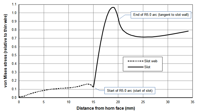
图 1 展示了一根 20 kHz、75 mm 宽 x 13 mm 厚的条形变幅杆中的槽应力分布。(槽宽 10 mm,起始端为完整的 5 mm 圆弧。槽腹长度为 15 mm。)请注意,应力从变幅杆端面开始逐渐上升,随后在槽处突然增大。就在槽圆弧与槽壁相切之前 4.1 mm 处,应力达到峰值。
重要提示 —— 除非另有说明 ——
- 槽应力可以按以下两种方式的任意一种或两种进行归一化 ——
- 相对于常规槽中的最高应力进行归一化。这显示了重新设计的槽相对于常规槽的改进程度。
- 相对于纵向谐振细线中的最高(波节处)应力进行归一化。该细线由与实际变幅杆相同的材料制成,并具有相同的输出振幅。图 1 展示的就是这样一条归一化应力曲线。此处相对应力曲线的最大值为 1.07。这意味着最大槽应力比纵向谐振细线中的最高应力高 7%。这样就可以在不受变幅杆材料、振幅和频率影响的情况下比较各种槽设计。
- 所有尺寸均针对 20 kHz 变幅杆。不过,这些尺寸可以很容易地按比例换算到其他频率。
- \( X \) 方向的尺寸平行于槽轴线(即轴向振动方向)。(在有限元分析模型中这是 \( Z \) 轴。)\( Y \) 方向的尺寸横向于槽轴线(即槽宽方向)。
|
|
|
降低槽应力的优点
降低槽应力可能带来以下几个优点 ——
- 在当前振幅下可以延长变幅杆的使用寿命。
- 现有变幅杆可以在更高的振幅下运行而不发生失效。
- 可以增大槽腹(即减小槽长),从而可能改善变幅杆的性能(更好的频率分离、更好的振幅均匀性、更低的横向振幅)。这取决于具体的变幅杆设计。
缺点是加工变得更复杂,成本也可能有所增加。
改进型槽
为了克服标准槽的应力局限,人们利用有限元分析对具有不同端部几何形状的槽进行了优化。所研究的几何形状包括复合圆弧、各种椭圆、悬链线和匙孔形。其他几何形状也是可能的,但可能不会带来显著的改进。在某些情况下(例如匙孔形),应力实际上明显更差。
设计考虑因素
槽的设计受到加工条件的约束。
- 槽应能用常规旋转刀具加工。(假定具备 CNC 能力,但并非绝对必需。)这样,大多数小型加工厂都能加工这些槽。这一标准排除了一些本来可以用线切割电火花加工或拉削来加工的潜在槽形(例如带尖端的槽)。
- 加工方式不应取决于变幅杆材料。这就排除了拉削,因为拉削并不特别适合钛。
- 与最佳加工方式相比,加工不应降低变幅杆的疲劳寿命。这通常会排除电火花加工。
- 槽应能加工到相当大的深度,例如在大型开槽块形变幅杆中。这就要求机床刀具(例如立铣刀)应尽可能刚硬(即大直径)。
基于上述标准,(优化端部之间的)槽的主壁应使用 Ø10.0 mm 刀具加工。选择 Ø8.0 mm 刀具来加工优化的槽端部。(曾研究过 Ø6.0 mm 刀具,但并未给出更好的结果。)
此外,所开发的槽设计应适用于许多不同的变幅杆设计,尽管它可能对每一种变幅杆设计都不是完全最优的。
优化
针对一根 20 kHz、75 mm 宽 x 13 mm 厚、带单个中央槽的条形变幅杆进行了槽优化。在杆的两端添加了 R10 mm 的纵向凹弧,以获得均匀的端面振幅(在 ±2% 以内);因此,该变幅杆在槽附近基本为轴向运动。该变幅杆还具有良好的频率分离。(这种宽度的变幅杆通常不需要开槽。之所以选择这根变幅杆作为测试案例,是因为它结构简单且性能良好。)
在上述变幅杆上完成优化后,又在其他变幅杆上测试了最优槽形,特别是一根 20 kHz 125 mm x 125 mm 的十字开槽块形变幅杆。
复合圆弧
标准的 5 mm 端部圆弧可以用两段相切圆弧替代 —— 在槽起始端处半径为 \( R_{1} \) 的较小圆弧,以及半径为 \( R_{2} \) 的较大连接圆弧,后者从较小圆弧过渡、并与槽壁相切收尾(即在槽宽为 10 mm 处相切)。两段圆弧在相接处彼此相切。
所需的 \( R_{2} \) 值由下式给出 ——
\begin{align} \label{eq:11500a} R_{2} = \frac{Y^2 - R_{1}^2 + (X_{w} - R_{1})^2}{2*(Y - R_{1})}\end{align}
式中 ——
| \( R_{2} \) | = 大连接圆弧的半径 |
| \( R_{1} \) | = 槽起始端处小圆弧的半径 |
| \( X_{w} \) | = 从槽起始端到大连接圆弧与槽壁相交点的距离 |
| \( Y \) | = 槽宽的 1/2 |
请注意,\( X_{w} \) 也是从槽起始端到大连接圆弧中心线的距离。
小圆弧与大圆弧彼此相切的点 \( (X_{t},Y_{t}) \) 由下式给出 ——
\begin{align} \label{eq:11510a} X_{t} = R_{1}*\sin\left( \theta \right)\end{align}
\begin{align} \label{eq:11520a} Y_{t} = R_{1}*\left\lgroup 1 - \cos\left( \theta \right) \right\rgroup\end{align}
式中 \( \theta \) 为小半径 \( R_{1} \) 在切点 \( (X_{t},Y_{t}) \) 处相对于槽轴线的夹角 ——
\begin{align} \label{eq:11530a} \theta = \sin^{-1}\left(\frac{R_{2} - Y}{R_{2} - R_{1}}\right)\end{align}
在上述各式中,\( (X,Y) \) 坐标系位于槽起始端处,\( X \) 轴与槽轴线重合,\( Y \) 轴垂直于槽轴线。
一般步骤是 ——
- 选择 \( R_{1} \) 和 \( Y \)。
- 在合理范围内选择 \( X_{w} \)(必须大于 \( Y \))。
- 根据上述参数计算 \( R_{2} \)。
- 建立有限元分析模型并分析槽应力。
- 重复以上步骤以找到最优参数。
示例 1
假定取下列数值 ——
| \( R_{1} \) | = 4 mm |
| \( Y \) | = 5 mm |
| \( X_{w} \) | = 10 mm |
则所需的连接半径 \( R_{2} \) 为 22.5 mm。小圆弧与大圆弧之间的切点位于 \( (X,Y) \) = (3.784,2.703),其中 \( \theta \) = 71.075°。
图 2 展示了 10 mm 宽槽在 \( R_{1} \) = 4 mm 时、若干 \( X_{w} \) 及相应 \( R_{2} \) 下的应力结果。表 1 给出了相应的槽参数。\( R_{2} \) = 12.5 mm 给出了最佳综合结果。
|
||||||||||||||||||||||||||||||||||||
|
槽腹长度的影响
该槽是针对 15 mm 长的槽腹进行优化的。然而,对其他槽腹长度的分析表明性能依然良好。图 N(a) 展示了三种不同槽腹长度下的槽应力。不出所料,随着槽腹长度的增加(即槽长减小),槽应力也随之增大,因为槽的起始端更靠近波节,而细线应力在波节处最高。图 N(b) 展示的是图 1(a) 的数据,但在这种情况下,每种槽的应力均相对于相同槽腹长度的常规槽进行了归一化。无论槽腹长度如何,每种槽在 R4 mm 小圆弧范围内的应力都基本相同。在大圆弧区域内,不同槽腹长度之间的应力存在一些差异,但并不显著。事实上,20 mm 槽腹长度的应力实际上还要略好一些。因此,为 15 mm 槽腹长度优化的槽也可以用于其他槽腹长度。
|
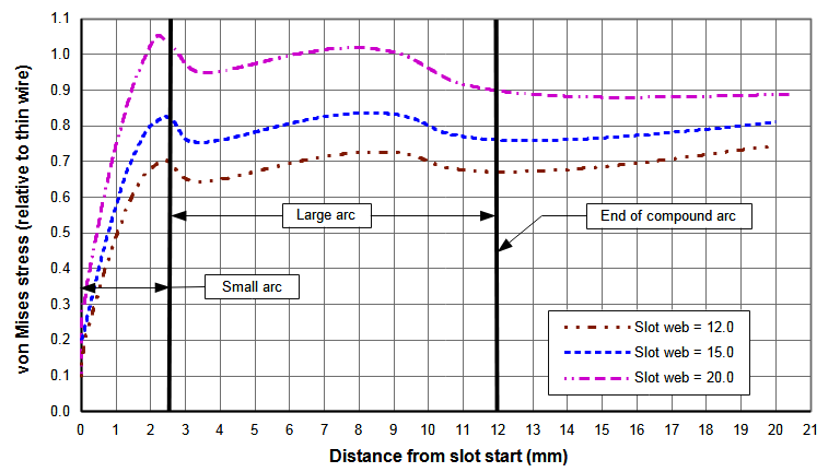
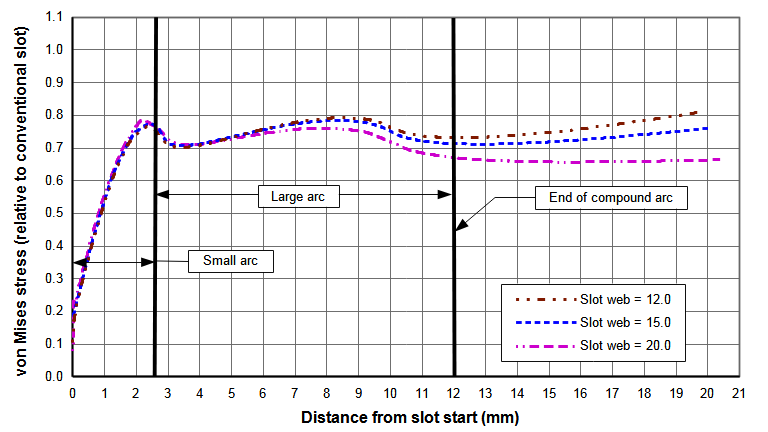
| 图 N. 槽腹长度对复合圆弧槽应力的影响 (20 kHz 75 mm 宽条形变幅杆,带一个 10 mm 宽槽) |
椭圆
各种不同程度的椭圆由以下方程描述(参见超椭圆(SuperEllipse))——
\begin{align} \label{eq:11590a} {{\huge\lgroup}{\frac{z - z_{0}}{a}}{\huge\rgroup}}^p + {{\huge\lgroup}{\frac{y - y_{0}}{b}}{\huge\rgroup}}^q = 1\end{align}
式中 ——
| \( X \) | = 沿椭圆长轴的曲线坐标 |
| \( y \) | = 沿椭圆短轴的曲线坐标 |
| \( z_{0}, y_{0} \) | = 椭圆中心的坐标 |
| \( a \) | = 椭圆长轴方向的半径 |
| \( b \) | = 椭圆短轴方向的半径 |
| \( p, q \) | = 决定 \( X \) 和 \( y \) 方向的曲率("方形度") |
表 2 展示了各椭圆参数之间的关系 ——
|
||||||||||||||||||||
|
匙孔形槽
匙孔形槽是指槽起始端处的槽横截面大于槽主壁横截面的槽。这类槽主要在采用线切割电火花加工槽的场合中尝试过。在这种情况下,较大的 电火花加工段的每一端都以相当大半径的圆弧收尾。例如,电火花加工段可能宽 XX mm,两端各以一个 R5 mm 圆弧收尾。
各种槽的对比
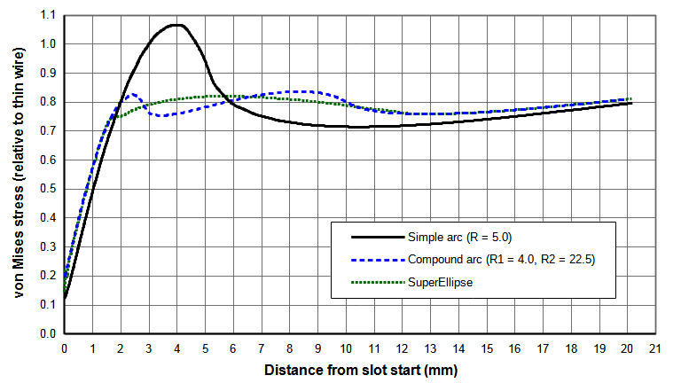
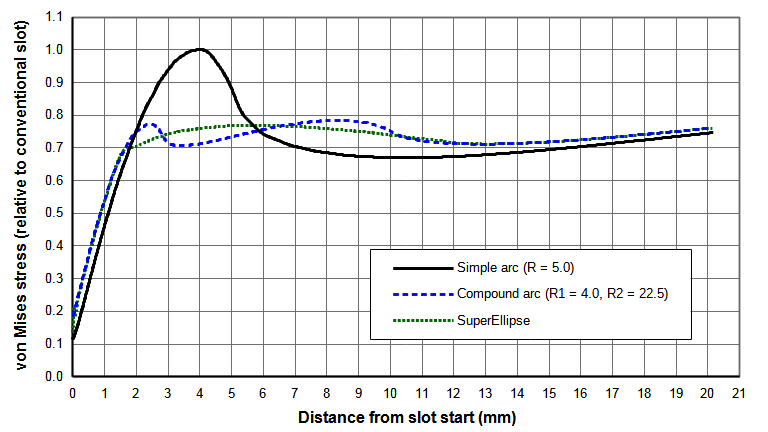
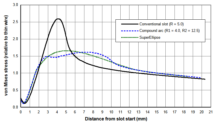
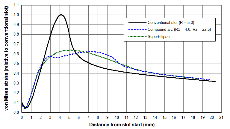
图 N 展示了几种槽构型之间的对比。超椭圆平滑的应力轮廓在观感上似乎比复合圆弧更美观。然而,与常规槽相比,两者给出的应力降低幅度相近(复合圆弧设计为 22%,超椭圆设计为 23%)。复合圆弧在 CNC 加工编程上应当更容易一些。不过,由于两者的轮廓非常相似,加工效果应当相当。
|
||||||||||
|
谐振频率的变化
当用优化设计替代标准槽时,谐振频率的变化极小。均匀性的变化也极小。表 3 展示了所分析变幅杆的情况。因此,优化设计可以直接替代常规设计。
|
||||||||||||||||||||||||
|
注意 —— \( f_1 \) 是在指定频率范围(16 kHz – 24 kHz)内的最低频率。它并不是该变幅杆可能达到的最低频率。\( f_n \)(指定频率范围内的最高频率)同理。
其他几何形状
Ciomber [1] 提出了几种用于降低轴向受载杆件应力的几何形状(见第 29 页)。Simões [1] 使用无梯度优化算法来改善疲劳试样中的应力。这是一种迭代方法,即用三次样条对槽进行建模,并逐个调整样条的控制点以达到最优状态 —— 在应力过高的位置将样条点向内调整(即去除材料),反之亦然。其中一些技术可以用于降低槽中的超声应力。Waldman 提出了超圆锥曲线(超椭圆、超抛物线等的推广),可以尝试。然而,由于目前的优化设计在离开 \( R4 \) 圆弧之后已经给出相当恒定的槽应力,在当前的设计约束下(特别是加工约束),这些替代几何形状似乎不太可能给出明显更好的结果。
在其他变幅杆上的应用
20 kHz 125 mm x 125 mm 块形变幅杆
对一根 20 kHz 125 mm x 125 mm 的块形变幅杆应用上述槽设计进行了分析。该变幅杆每个面上有两个槽。每个槽都与相邻面上的横向槽相交。图 N 展示了槽应力结果。常规相交槽中的最高应力是测试条形变幅杆中不相交槽的 2.4 倍(将图 N(a) 与图 N(a) 对比)。带复合圆弧的槽将这一应力降低了 38%,而带超椭圆的槽将这一应力降低了 36%(图 N(b))。
|
||||||||||
|
Slot optimization - Under development
Contents
- Introduction
- Standard slots
- Advantages of reduced slot stress
- Advanced slots
- Optimization
- Application to other horns
- Figures
- Figure 1. Figure_title
- Tables
- Table 1. Table_title
Introduction
As the lateral dimensions of horns become large (relative to the thin-wire half wavelength), Poisson coupling near the node distorts the face amplitude. If the lateral dimensions become sufficiently large then the longitudinal resonance may disappear entirely — nodes will appear on the face and/or stud surfaces.
To alleviate this problem, wide horns have slots that are aligned parallel to the direction of longitudinal vibration. The slot length is a considerable portion of the half wavelength.
Unfortunately, these slots introduce stress concentrations which may cause fatigue failures toward slot starts.
Standard slots
At 20 kHz the slots are typically 10 mm wide with a full 5 mm radius at each end. (Wider slots 12–13 mm can be used but these may cause performance problems.) Toward the horn's output face the slot web length is typically between 12 mm and 20 mm. Toward the horn's input surface the slot web may be considerably larger if the horn is designed with gain.
Figure 1 shows the slot stress distribution in a 20 kHz 75 mm wide x 13 mm thick bar horn. (The slot is 10 mm wide with a full 5 mm radius at the start. The web length is 15 mm.) Note the gradual stress rise from the horn's face and then the sudden stress increase at the slot. The stress peaks at 4.1 mm just before the slot arc becomes tangent to the slot wall.
Important — Unless otherwise noted —
- Slot stresses may be normalized in either or both of two manners —
- Normalized with respect to the highest stress in a conventional slot. This shows the relative improvement of the redesigned slot compared to a conventional slot.
- Normalized with respect to the highest (nodal) stress in a longitudinally resonant thin wire. The thin wire is made of the same material and has the same output amplitude as the actual horn. Figure 1 shows a normalized stress curve. Here the maximum value of the relative stress curve is 1.07. This means that the maximum slot stress is 7% higher than the highest stress in a longitudinally resonant thin wire. This allows for comparison of various slot designs that are independent of the horn's material, amplitude, and frequency.
- All dimensions are for 20 kHz horns. However, these can easily be scaled to other frequencies.
- \( X \) dimensions are parallel to the slot axis (i.e., in the direction of axial vibration). (In the FEA models this is the \( Z \) axis.) \( Y \) dimensions are transverse to the slot axis (in the direction of the slot width).
|
|
|
Advantages of reduced slot stress
Reducing the slot stress may have several advantages —
- The horn life may be extended at the current amplitude.
- The existing horn can be run at a higher amplitude without failure.
- The slot web can be increased (i.e., reduced slot length) which may improve the horn's performance (better frequency separation, better amplitude uniformity, reduced transverse amplitude). This will depend on the particular horn design.
The disadvantage is that machining becomes more complex and possibly more somewhat more costly.
Advanced slots
In order to overcome the stress limitations of standard slots, slots with different termination geometries have been optimized with finite element analysis. The investigated geometries include compound arcs, various ellipses, catenaries, and keyholes. Other geometries are possible but may not yield significant improvements. In some cases (e.g., keyholes) the stresses were actually significantly worse.
Design considerations
The slot design was constrained by machining considerations.
- The slots should be machinable using conventional rotary tools. (CNC capability was assumed but not absolutely required.) Then these slots could be machined by most small shops. This criterion eliminated some potential slot geometries (e.g., a slot with a pointed end) that could have been machined by wire EDM or broaching.
- The machining should not depend on the horn material. This eliminated broaching which isn't particularly suited to titanium.
- The machining should not reduce the fatigue life of the horn compared to optimal machining practices. This would usually eliminate EDM.
- The slots should be machinable to considerable depths such as in large slotted block horns. This requires that the machine tool (e.g., end mill) should be as rigid as possible (i.e., large diameter).
Based on the above criteria, the main slot walls (between the optimized terminations) should be machined with a Ø10.0 mm tool. A Ø8.0 mm tool was chosen to machine the optimized slot terminations. (A Ø6.0 mm tool was investigated but didn't give better results.)
In addition, the developed slot design should be suitable for many different horn designs, even though it may not be quite optimal for every horn design.
Optimization
Slots were optimized for a 20 kHz 75 mm wide x 13 mm thick bar horn with a single center slot. R10 mm flutes were added to the ends to give uniform face amplitudes (within ±2%); hence, this horn has essentially axial motion near the slot. This horn also has good frequency separation. (A horn of this width would typically not need a slot. This horn was chosen as a test case based on its simplicity and good performance.)
After optimizing with the above horn, the optimal slots were tested on other horns, in particular a 20 kHz 125 mm x 125 mm cross-slotted block horn.
Compound arcs
The standard 5 mm terminating arc can be replaced with two tangential arcs — a smaller arc with radius \( R_{1} \) at the slot start and a larger connecting arc with radius \( R_{2} \) that transitions from the smaller arc to a tangential termination at the slot wall (i.e., at a slot width of 10 mm). The two arcs are tangent to each other where they meet.
The required value of \( R_{2} \) is given by —
\begin{align} \label{eq:11500a} R_{2} = \frac{Y^2 - R_{1}^2 + (X_{w} - R_{1})^2}{2*(Y - R_{1})}\end{align}
where —
| \( R_{2} \) | = radius of the large connecting arc |
| \( R_{1} \) | = radius of the small arc at slot start |
| \( X_{w} \) | = distance from the slot start to the point where the large connecting arc intersects the slot wall |
| \( Y \) | = 1/2 of the slot width |
Note that \( X_{w} \) is also the distance from the slot start to the centerline of the large connecting arc.
The point \( (X_{t},Y_{t}) \) where the small and large arcs are tangent to each other is given by —
\begin{align} \label{eq:11510a} X_{t} = R_{1}*\sin\left( \theta \right)\end{align}
\begin{align} \label{eq:11520a} Y_{t} = R_{1}*\left\lgroup 1 - \cos\left( \theta \right) \right\rgroup\end{align}
where \( \theta \) is the angle of the small radius \( R_{1} \) at the tangency point \( (X_{t},Y_{t}) \) with respect to the slot axis —
\begin{align} \label{eq:11530a} \theta = \sin^{-1}\left(\frac{R_{2} - Y}{R_{2} - R_{1}}\right)\end{align}
In the above equations, the \( (X,Y) \) coordinate system is located at the slot start with the \( X \) axis aligned with the slot axis and the \( Y \) axis perpendicular to the slot axis.
The general approach is —
- Choose \( R_{1} \) and \( Y \).
- Choose \( X_{w} \) within a reasonable range (must be greater than \( Y \)).
- Calculate \( R_{2} \) based on the above parameters.
- Build the FEA model and analyze the slot stresses.
- Repeat above to find optimal parameters.
Example 1
Assume the following values —
| \( R_{1} \) | = 4 mm |
| \( Y \) | = 5 mm |
| \( X_{w} \) | = 10 mm |
Then the required connecting radius \( R_{2} \) is 22.5 mm. The tangent point between the small and large arcs occurs at \( (X,Y) \) = (3.784,2.703) where \( \theta \) = 71.075°.
Figure 2 shows the stress results for a 10 mm wide slot with \( R_{1} \) = 4 mm and several \( X_{w} \) and associated \( R_{2} \). Table 1 gives the associated slot parameters. \( R_{2} \) = 12.5 mm gives the best overall results.
|
||||||||||||||||||||||||||||||||||||
|
Effect of web length
The slot has been optimized for a 15 mm long slot web. However, analyses at other slot web lengths shows that the performance remains good. Figure N(a) shows the slot stresses for three different web lengths. As expected, as the web length increases (i.e., the slot length decreases) the slot stress also increases since the slot starts closer to the node where the thin-wire stess is highest. Figure N(b) shows the data from figure 1(a) but in this case the stresses of each slot have been normalized with respect to a conventional slot with the same web length. Regardless of the web length, each slot has essentially identical stresses within the R4 mm small arc. Within the region of the large arc there is some stress variation among the slot web lengths but nothing substantial. In fact, the stresses for the 20 mm web length are actually somewhat better. Hence, the slot that was optimized for the 15 mm web length can be used for other web lengths.
|
| Figure N. Effect of web length on slot stresses for compound radii (20 kHz 75 mm wide bar horn with one 10 mm wide slot) |
Ellipses
Ellipses of varying degrees are described by the following equation (see SuperEllipse) —
\begin{align} \label{eq:11590a} {{\huge\lgroup}{\frac{z - z_{0}}{a}}{\huge\rgroup}}^p + {{\huge\lgroup}{\frac{y - y_{0}}{b}}{\huge\rgroup}}^q = 1\end{align}
where —
| \( X \) | = curve coordinate along major ellipse axis |
| \( y \) | = curve coordinate along minor ellipse axis |
| \( z_{0}, y_{0} \) | = coordinates of the ellipse center |
| \( a \) | = radius of major ellipse span |
| \( b \) | = radius of minor ellipse span |
| \( p, q \) | = determines the curvatures ("squareness") in the \( X \) and \( y \) directions |
Table 2 shows the relationship between the various ellipse parameters —
|
||||||||||||||||||||
|
Keyhole slots
Keyhole slots are those for which the slot cross-section at the slot start is larger than the cross-section of the main slot walls. These have mainly been tried where the slots have been machined by wire EDM. In this case the large Each end of the EDM terminates in an arc of substantial radius. For example, EDM section may be XX mm wide terminating at each end in a R5 mm arc.
Slot comparisons
Figure N shows comparisons between the several slot configurations. The smooth stress contour of the superellipse seems aesthetically more pleasing than the compound arc. However, both give similar stress reductions compared to a conventional slot (22% for the compound arc design versus 23% for the superellipse design). The compound arc should be somewhat easier to program for CNC machining. However, both should machine equally since their contours are very similar.
|
||||||||||
|
Changes in resonant frequencies
When a standard slot is replaced by an optimized design, the resonant frequencies show minimal change. Also, the uniformities show minimal change. Table 3 shows this for the analyzed horn. Hence, an optimized design can be directly substituted for the conventional design.
|
||||||||||||||||||||||||
|
Note — \( f_1 \) is the lowest frequency within the specified frequency range (16 kHz – 24 kHz). It is not the lowest possible frequency for this horn. Similarly for \( f_n \) (the highest frequency within the specified frequency range).
Other geometries
Ciomber [1] presents several proposed geometries for reducing stress in an axially loaded bar (see p. 29). Simões [1] uses a gradientless optimization algorithm to improve the stress in fatigue test specimens. This is an iterative approach whereby the slot is modeled with a cubic spline and the spline's control points are individually adjusted to achieve the optimum condition — where the stress is too high the spline point is adjusted inward (i.e., remove material) and vice versa. Some of these techniques could be applied toward reducing ultrasonic stresses in slots. Waldman presents a superconic (generalization of superellipse, superparabola, and others) that could be tried. However, since the current optimized designs give reasonably constant slot stresses after exiting the \( R4 \) arc, it seems unlikely that these alternate geometries would give substantially better results within the current design constraints (particularly for machining).
Application to other horns
20 kHz 125 mm x 125 mm block horn
A 20 kHz 125 mm x 125 mm block horn was analyzed with the above slot designs. This horn had two slots on each face. Each slot intersected a transverse slot from an adjoining face. Figure N shows the slot stress results. The highest stress in the conventional intersected slot is 2.4 times greater than for the non-intersected slot in the test bar horn (compare figure N(a) to figure N(a)). The slot with the compound arc reduces this stress by 38% while the slot with the SuperEllipse reduces this stress by 36% (figure N(b)).