组合变幅杆
组合变幅杆是一种全波变幅杆,由至少两个子变幅杆组成,并由一个母变幅杆驱动。组合变幅杆用于普通变幅杆不适用的场合 — 即必须把高焊接振幅集中在间距很大的多个位置,或者需要很深的让位空间的场合。
|
|
|
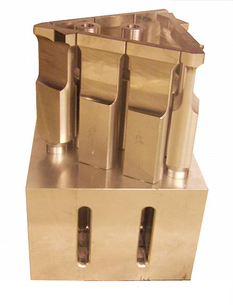
设计准则
以下是一些设计准则。
- 确定母变幅杆。母变幅杆单独工作时应有良好的性能(即端面轴向振幅均匀、横向振幅最小、轴向谐振与次级谐振之间有良好的频率间隔,以及可接受的寿命)。最佳母变幅杆的选择取决于频率、形状和尺寸。由于这些因素相互影响,可能需要一些试错评估。
- 频率。对于给定的母变幅杆尺寸,较低的频率通常会带来更好的性能,因为半波长与横向尺寸之比更大。例如,假设母变幅杆材料为铝,其波速约为 5000 m/sec。那么在 20 kHz 时半波长为 125 mm,而在 15 kHz 时半波长为 167 mm。如果假定母变幅杆尺寸为 150 mm x 150 mm(无论频率如何),那么半波长与横向尺寸之比在 20 kHz 时为 0.83,而在 15 kHz 时为 1.11。
(上述讨论是一般性概括,并不总是成立。同样,可能需要一些试错评估。) - 形状。圆柱形和块形变幅杆都应予以考虑。例如,如果子变幅杆呈圆形排布,首先想到的可能是圆柱形母变幅杆;然而,类似的块形变幅杆实际上可能有更好的性能。
- 尺寸。母变幅杆的最佳尺寸可能需要比子变幅杆的排布范围稍大一些。例如,子变幅杆可能被限制在 130 mm x 130 mm 的区域内。然而,150 mm x 150 mm 的母变幅杆可能比 130 mm x 130 mm 的母变幅杆性能更好。
- 频率。对于给定的母变幅杆尺寸,较低的频率通常会带来更好的性能,因为半波长与横向尺寸之比更大。例如,假设母变幅杆材料为铝,其波速约为 5000 m/sec。那么在 20 kHz 时半波长为 125 mm,而在 15 kHz 时半波长为 167 mm。如果假定母变幅杆尺寸为 150 mm x 150 mm(无论频率如何),那么半波长与横向尺寸之比在 20 kHz 时为 0.83,而在 15 kHz 时为 1.11。
- 确定母变幅杆材料。如果应力足够低,较大的母变幅杆应采用铝材。这将降低材料和加工成本,并减少启动困难(因为质量更小)。有人建议,如果子变幅杆是钢制的,母变幅杆应采用钛材。(考虑钢制子变幅杆可能是因为潜在的磨损问题。不过,也可以改用带可更换端头或硬质合金端面的钛制子变幅杆。)
- 考虑子变幅杆的排布。子变幅杆的布置应使其在母变幅杆端面上相对均衡。这可能需要使用比正常稍大的母变幅杆。
子变幅杆的排布可能需要稍微平移或旋转,使螺柱最好不要与母变幅杆上的槽相交,否则可能导致母变幅杆的疲劳失效。或者,如果不会显著损害性能,也可以调整母变幅杆上槽的位置。
如果有源子变幅杆无法排布成相对均衡的图案,则可能需要虚设(无源)子变幅杆来进行补偿。 这些变幅杆可以采用任何合适的形状,只要不与其他子变幅杆或塑料件发生干涉即可。 - 确定子变幅杆材料。子变幅杆通常由钛制成,但这取决于应用。
- 确定接头接触直径。无论子变幅杆尺寸如何,在子变幅杆的螺柱端面上采用小的接触垫(加工的垫圈)可能获得最佳效果。例如,在某支 20 kHz 组合变幅杆上使用了直径 20 mm 的接触垫。通过减小接触面积,小接触垫可以降低子变幅杆的横向运动,从而减少损耗和接头问题。如果子变幅杆是条形变幅杆,尤其应采用接触垫。(见图 1 和图 4 中的条形变幅杆。)接触垫的高度只需足以容纳后续整修时的材料去除量即可。例如,1 mm 高度(甚至更小)就足够了。
- 选择子变幅杆形状。只要可能,子变幅杆应采用圆柱形或带平面的圆柱形,以便在紧固时不会与相邻子变幅杆碰撞。当然,如果子变幅杆的间距足够大以避免此类干涉,这就不是问题。
- 调谐子变幅杆。所有子变幅杆都应调谐到非常接近的同一频率(对于 20 kHz 设计,约在 ±10 Hz 以内)。否则,可能出现双轴向谐振(即一些子变幅杆振幅高,而另一些因子幅杆未在正确频率下工作而振幅低)。
- 紧固子变幅杆。
- 为子变幅杆编号。组装后应为每个子变幅杆编号。同样的编号应标注在母变幅杆上紧邻该子变幅杆的位置。如果因子幅杆维修(如修整接头表面)而必须拆下,这将有助于重新组装。
- 最终加工。在某些情况下,子变幅杆组装到母变幅杆上之后,还必须对其端面进行一些最终加工。然而,由于此时子变幅杆得不到良好支撑,加工时可能产生颤振,进而可能无法与塑料件正确贴合。为防止这种颤振,可以在加工前将子变幅杆浇注封装在 Flexane(柔性聚氨酯浇注材料)中。全部加工完成后再去除该浇注体。
子变幅杆的定向
除子变幅杆为轴对称的情况(如铆焊变幅杆)外,每个子变幅杆都必须定向,使其端面相对于塑料件正确就位。由于子变幅杆通常用螺纹拧到变幅杆端面上,它们的初始朝向很可能是不正确的。
可自由旋转的子变幅杆
圆柱形子变幅杆和(通常)带平面的圆柱形变幅杆可以自由旋转而不会与其他子变幅杆干涉。对于这类变幅杆,调整朝向的最佳方法是使用差动螺距螺柱(即两端螺距不同的螺柱)。差动螺纹用于阶梯螺柱;不过,对于当前用途而言,阶梯并非必需。
|
|
|
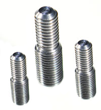
用一个示例可以最好地说明这种方法。假设螺柱一端的螺距为 1.25 mm,另一端的螺距为 1.5 mm。再假设 1.25 mm 螺纹拧在子变幅杆中,而 1.5 mm 螺纹拧在母变幅杆中。子变幅杆紧固到母变幅杆上之后,设想把螺柱锁定在母变幅杆上。现在将子变幅杆松开 1/4 圈(逆时针 90°),使子变幅杆与母变幅杆之间产生 0.3125 mm(即 1/4 x 1.25 mm)的间隙。然后把螺柱改为锁定在子变幅杆上,而不是母变幅杆上。接着拧紧子变幅杆时,间隙将借助母变幅杆中的 1.5 mm 螺距闭合。这需要顺时针旋转 75° — 即 (0.3125 mm / 1.5 mm) * 360°。因此,子变幅杆相对于其原始位置的净重新定向为逆时针 15°。子变幅杆的净重新定向可按下式计算 —
\begin{align} \label{eq:10601a} \measuredangle_t = \measuredangle_s \left( 1 - \frac {p_t}{p_m}\right) \end{align}
式中 —
| \( p_t \) | = 子变幅杆中螺纹的螺距 |
| \( p_m \) | = 母变幅杆中螺纹的螺距 |
| \( \measuredangle_s \) | = 螺柱相对于子变幅杆转过的角度 |
| \( \measuredangle_t \) | = 子变幅杆相对于母变幅杆转过的净角度 |
逆时针旋转(按右手定则)时角度为正。因此,对于上述示例 —
\begin{align} \label{eq:10602a} \measuredangle_t &= 90° \left( 1 - \frac {1.25~\textrm{mm}}{1.50~\textrm{mm}}\right) \\ &= 15° \nonumber \end{align}
如果子变幅杆的定向偏差角 \( \measuredangle_t \) 已经确定,那么所需的螺柱旋转角为 —
\begin{align} \label{eq:10603a} \measuredangle_s = \large\frac {\measuredangle_t} {\left( 1 - \frac {p_t}{p_m}\right)} \end{align}
实际过程与上述示例不同。
- 螺柱在子变幅杆中保持浮动(不拧到底),以便后续对子变幅杆进行旋转调整。
- 螺柱在子变幅杆中半固定,以防子变幅杆向母变幅杆上拧紧时螺柱随之转动(例如用中等强度螺纹锁固胶、在拧入前使螺柱螺纹轻微变形等)。
- 将子变幅杆紧固到母变幅杆上。确定子变幅杆的定向偏差角。
- 由公式 \eqref{eq:10603a} 计算螺柱必须转过的角度。
- 转动螺柱。
- 重复步骤 3 至 5,直到子变幅杆正确定向。
注 — 在使用此步骤之前,应将子变幅杆在母变幅杆上反复拧紧数次。这会使母变幅杆的螺纹就位。否则,如果螺纹没有充分就位,子变幅杆在螺柱调整后会转过比预期更大的角度。
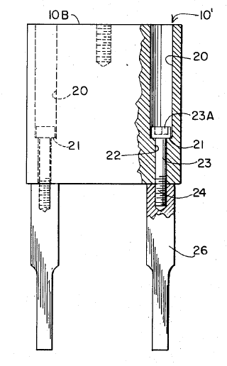
另一种方法是,用插入母变幅杆背面沉孔中的螺栓来紧固子变幅杆。这是 Davis[1] 在其原始专利中提出的方法之一(见图 3)。尽管这种方法可以快速调整变幅杆朝向,但它可能引起其他问题,例如螺栓头下方发热。
|
|
|
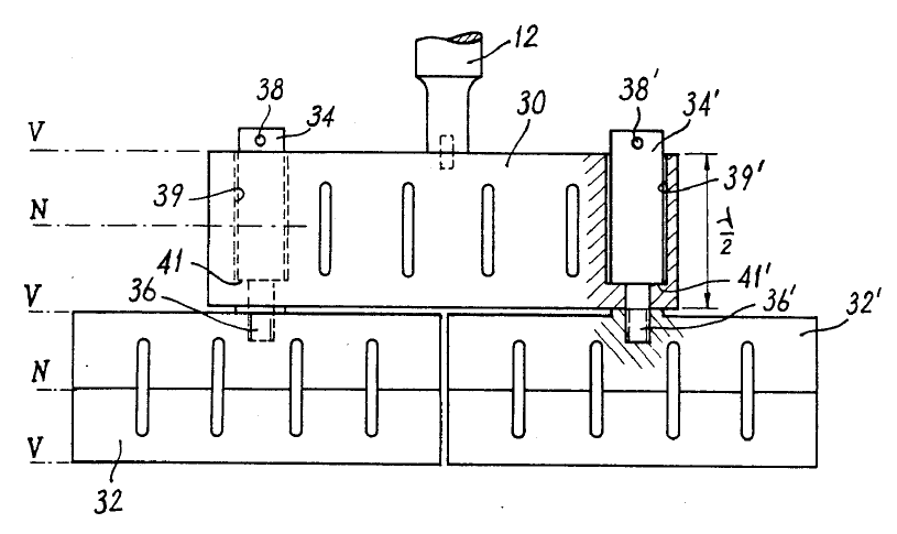
Scotto[2] 提出用带外凸螺柱的调谐半波杆来替代螺栓(图 4)。然而,这引入了其他问题。
- 需要在母变幅杆上进行大量沉孔加工以容纳这些杆。
- 从母变幅杆上去除的材料可能使母变幅杆失衡,从而产生不理想的端面振幅。
- 对于某些开槽变幅杆,如果沉孔会与槽相交,这种方法可能不适用。
- 这些杆可能引入额外的不期望的弯曲模态。
|
|
|
旋转受阻的子变幅杆
在某些情况下,子变幅杆的设计使其无法在不与相邻变幅杆碰撞的情况下旋转,因而也就无法通过旋转来紧固。这些通常是彼此靠得很近的条形变幅杆。在这种情况下,可以考虑上述 Davis 和 Scotto 的方法。
Composite horns
Contents
A composite horn is a full-wave horn consisting of at least two tip horns driven by a mother horn. A composite horn is used where normal horns are not feasible — where high welding amplitude must be concentrated at widely spaced locations or when a deep relief is needed.
|
|
|
Design guidelines
The following are some design guidelines.
- Specify the mother horn. The mother horn should have good performance when operated alone (i.e., uniform face axial amplitude, minimum transverse amplitude, good frequency separation between the axial resonance and secondary resonances, and acceptable life). The choice of optimum mother horn will depend on the frequency, shape, and size. Since these factors interact, some trial-and-error evaluation may be needed.
- Frequency. For a given mother horn size, a lower frequency will often give better performance since the ratio of half-wavelength to lateral dimension is larger. For example, assume the mother horn material is aluminum for which the wave speed is approximately 5000 m/sec. Then at 20 kHz the half-wavelength would be 125 mm whereas at 15 kHz the half-wavelength would be 167 mm. If the assumed mother horn size is 150 mm x 150 mm (regardless of the frequency) then the ratio of half-wavelength to lateral dimension would be 0.83 at 20 kHz versus 1.11 at 15 kHz.
(The above discussion is a generalization and is not always true. Again, some trial-and-error evaluation may be needed.) - Shape. Both cylindrical and block horns should be considered. For example, if the tip horns form a circular pattern then a cylindrical mother horn might be the first thought; however, a similar block horn might actually have better performance.
- Size. The optimal mother horn size may need to be somewhat larger than the pattern of the tip horns. For example, the tip horns might be confined to a 130 mm x 130 mm area. However, a 150 mm x 150 mm mother horn might give better performance than a 130 mm x 130 mm mother horn.
- Frequency. For a given mother horn size, a lower frequency will often give better performance since the ratio of half-wavelength to lateral dimension is larger. For example, assume the mother horn material is aluminum for which the wave speed is approximately 5000 m/sec. Then at 20 kHz the half-wavelength would be 125 mm whereas at 15 kHz the half-wavelength would be 167 mm. If the assumed mother horn size is 150 mm x 150 mm (regardless of the frequency) then the ratio of half-wavelength to lateral dimension would be 0.83 at 20 kHz versus 1.11 at 15 kHz.
- Specify the mother horn material. If the stresses are sufficiently low then larger mother horns should be aluminum. This will reduce material and machining costs and reduce starting difficulties (because of reduced mass). It has been suggested that if the tip horns are steel then the mother horn should be titanium. (Steel tip horns might be considered because of potential wear problems. However, titanium tip horns with replaceable tips or carbide faces might be used instead.)
- Consider the pattern of the tip horns. The tip horns should be positioned so that they are relatively balanced on the face of the mother horn. This may require using a somewhat larger mother horn than normal.
The pattern of the tip horns may need to be shifted or rotated slightly so tha the studs preferably do not intersect slots in the mother horn which could cause fatigue failures in the mother horn. Alternately, the slot locations in the mother horn can be adjusted if this would not significantly adversely affect the performance.
If the active tip horns can't be arranged in a relatively balanced pattern then dummy (inactive) tip horns may be needed in order to compensate. These horns can have any suitable shape as long as they don't interfere with other tip horns or with the plastic part. - Specify the tip horn material. Tip horns are often made of titanium but this will depend on the application.
- Specify the joint contact diameter. Regardless of the size of the tip horns, a small contact pad (machined washer) on the tip horn's stud surface may give optimum results. For example, on one 20 kHz composite horn a 20 mm diameter contact pad was used. By decreasing the contact area, a small contact pad can reduce the transverse motion of the tip horns, thereby reducing losses and joint problems. The contact pad should particularly be used if the tip horns are bar horns. (See the bar horns of figures 1 and 4.) The height of the contact pad only needs to be sufficient to accommodate subsequent material removal during reconditioning. For example, 1 mm height (or even less) should be sufficient.
- Choose the tip horn shape. Whenever possible, the tip horns should be cylindrical or flatted cylindrical so that they can be tightened without colliding with adjacent tip horns. Of course, this is not a problem if the spacing of the tip horns is large enough to avoid such interference.
- Tune the tip horns. All tip horns should be tuned very closely to the same frequency (within approximately ±10 Hz for a 20 kHz design). Otherwise, double-axial resonances may result (where some tip horns have high amplitude while others have low amplitude because they are not operating at the correct frequency).
- Tighten the tip horns.
- Number the tip horns. After assembly each of the tip horns should be numbered. The same number should be placed on the mother horn adjacent to the tip horn location. This will assist in reassembling if the tip horns must be removed for servicing (e.g., to dress the joint surfaces).
- Finished machining. In some cases some final machining must be done to the faces of the tip horns after assembly to the mother horn. However, because a tip horn is not well supported in this situation, it may chatter during machining and then may not properly fit the plastic part. To prevent this chatter the tip horns can be encased in a poured flexane cast prior to machining. This cast is then removed after all machining is complete.
Orienting the tip horns
Except in the case where the tip horns are axisymmetric (e.g., staking horns), each tip horn must be oriented so that its face is correctly positioned with respect to the plastic part. Because the tip horns are typically screwed to the horn face, their initial orientations will likely be incorrect.
Tip horns that can be freely rotated
Cylindrical tip horns and (usually) flatted-cylindrical horns can be freely rotated without interfering with other tip horns. For such horns the best method to adjust the orientation is to use a stud with a differential thread pitch (i.e., a stud with different thread pitches on each end). Differential threads are used in step studs; however, the step would not necessarily be required for the current use.
|
|
|
This method can be best illustrated with an example. Assume one end of the stud has a 1.25 mm pitch while the other end has a 1.5 mm pitch. Now assume that the 1.25 mm thread is in the tip horn while the 1.5 mm thread is in the mother horn. After the tip horn has been tightened to the mother horn, imagine that the stud is locked to the mother horn. Now the tip horn is loosened 1/4 turn (90° counterclockwise) so that a gap of 0.3125 mm (i.e., 1/4 x 1.25 mm) is created between the tip horn and the mother horn. The stud is then locked to the tip horn instead of the mother horn. Then when the tip horn is tightened the gap will be closed by using the 1.5 mm thread pitch in the mother horn. This will require a tightening rotation of 75° clockwise — i.e., (0.3125 mm / 1.5 mm) * 360°. Thus, the net reorientation of the tip horn would be 15° counterclockwise from its original position. The net reorientation of the tip horn can be calculated as —
\begin{align} \label{eq:10601a} \measuredangle_t = \measuredangle_s \left( 1 - \frac {p_t}{p_m}\right) \end{align}
where —
| \( p_t \) | = Pitch of thread in tip horn |
| \( p_m \) | = Pitch of thread in mother horn |
| \( \measuredangle_s \) | = Angle through which the stud is rotated relative to the tip horn |
| \( \measuredangle_t \) | = Net angle through which the tip horn is rotated relative to the mother horn |
The angles are positive when the rotation is counter clockwise (per the right hand rule). Thus, for the above example —
\begin{align} \label{eq:10602a} \measuredangle_t &= 90° \left( 1 - \frac {1.25~\textrm{mm}}{1.50~\textrm{mm}}\right) \\ &= 15° \nonumber \end{align}
If the angle of tip horn mis-orientation \( \measuredangle_t \) has been determined, then the required angle of stud rotation is —
\begin{align} \label{eq:10603a} \measuredangle_s = \large\frac {\measuredangle_t} {\left( 1 - \frac {p_t}{p_m}\right)} \end{align}
The actual process is different than in the above example.
- The stud is floated (not bottomed) in the tip horn to allow subsequent rotational adjustment of the tip horn.
- The stud is semi-secured in the tip horn to prevent it from rotating as the tip horn is tightened to the mother horn (e.g., with a medium thread locking compound, by distorting the stud threads prior to insertion, etc.).
- The tip horn is tightened to the mother horn. The angle by which the tip horn is mis-oriented is determined.
- The angle by which the stud must be rotated is calculated from equation \eqref{eq:10603a}.
- The stud is rotated.
- Repeat steps 3 through 5 until the tip horn is correctly oriented.
Note — Before using this procedure the tip horn should be torqued several times into the mother horn. This will seat the mother horn threads. Otherwise, if the threads have not been adequately seated then the tip horn will turn farther than expected after the stud adjustment.
Alternately, the tip horn can be tightened with a bolt that is inserted in a counterbored hole in the back of the mother horn. This is one approach that was suggested by Davis[1] in his original patent (see figure 3). Although this allows quick orientation of the horn it can cause other problems such as heating under the bolt head.
|
|
|
Scotto[2] proposed replacing the bolts with tuned half-wave rods with protruding studs (figure 4). However, this introduces other problems.
- Substantial counterbore machining of the mother horn is required to accommodate the rods.
- The material that is machined from the mother horn may unbalance the mother horn, thereby giving it undesirable face amplitudes.
- This may not be suitable for some slotted horns where the counterbores would intersect the slots.
- The rods may introduce additional undesired flexure modes.
|
|
|
Tip horns that are blocked from rotating
In some cases the tip horn design is such that it can't be rotated without colliding with adjacent horns. Then it can't be tightened by rotating. These are usually bar horns that sit close together. In this case the methods of Davis and Scotto (above) could be considered.