增益
定义
一般而言(对于任何系统):
\begin{align} \label{eq:10501a} \textsf{Gain} = \frac{\textsf{Output}}{\textsf{Input}} \end{align}
对于超声谐振器,增益表示振幅之比:
\begin{align} \label{eq:10502a} \textsf{Gain} = \frac{\textsf{Output amplitude}}{\textsf{Input amplitude}} \end{align}
或者,有时表示速度之比:
\begin{align} \label{eq:10503a} \textsf{Gain} = \frac{\textsf{Output velocity}}{\textsf{Input velocity}} \end{align}
对于给定的谐振器,公式 \eqref{eq:10502a} 和 \eqref{eq:10503a} 给出相同的值。
除非另有说明:
- 所有振幅均沿主(期望)方向。
- 对于轴向谐振器,相关振幅为轴向振幅。
- 对于径向圆盘谐振器,输入振幅可能是径向的也可能是轴向的,取决于设计。输出振幅是圆盘外缘处的径向振幅。
- 对于弯曲谐振器,输入振幅为轴向。输出振幅为弯曲振幅。
- 输出振幅在端面中心测量。
- 输入振幅在螺柱表面中心测量。
如果说某个谐振器具有增益但未给出具体数值,则假定其增益大于 1.0(即正向增益)。(如果增益小于 1.0,则称该谐振器具有反向增益。)
理论
对于任何不受外力作用的振动系统,动量必须守恒。对于一个简单的轴向谐振器,任何横向运动都可以忽略……
对于一个半波谐振器,其阶跃恰好位于波节处,输入段和输出段均为等截面(横截面积恒定),且由单一材料制成,其理论增益就等于输入面积与输出面积之比。
\begin{align} \label{eq:10507a} {\textsf{Gain}}_{\textsf{theoretical}} = \textsf{Area ratio} \end{align}
其中 —
\begin{align} \label{eq:10508a} \textsf{Area ratio} &= \frac{\textsf{Area of input surface}}{\textsf{Area of output surface}} \end{align}
局限性
增益的定义只考虑主方向的振幅。因此,对于轴向谐振器,计算出的增益没有考虑横向运动。然而,这种横向运动对应用可能很重要。例如,许多钟形变幅杆具有可观的横向运动。这种运动对空化或消泡有帮助。然而,它对塑料焊接不利,因为它可能导致零件表面留下压痕(伴随过大的功率消耗)以及焊接不良。此外,这种横向运动还会增加显著的额外应力。因此,谐振器不能仅凭增益直接进行比较。
组合式变幅杆。
对高增益变幅杆的偏好
对于两个输出面积相同的变幅杆,可以证明增益较高的变幅杆储能较低,尽管其质量更大。(见附录 zzz。)因此,对于难以启动的大型变幅杆,高增益变幅杆更为可取。
对于给定的输出振幅,高增益变幅杆所需的输入振幅更低。这意味着变幅杆与增幅杆的连接处应力更低,在需要整修之前可以使用更长时间。这也意味着可以使用增益更低(应力更低)的增幅杆,从而增幅杆或许可以用铝而不是钛来制造。
测量
钛标准变幅杆。中间反馈换能器。
对于某些变幅杆(例如,端面带腔的钟形变幅杆),可能无法在变幅杆端面中心测量振幅。在其他情况下,可能最好在另一位置规定增益。例如,如果某个变幅杆只设计为沿其端面周边进行焊接,那么即使端面中心可以测量,最有意义的做法也是在该周边区域测量输出振幅。在这种情况下,必须指明增益测量的位置(例如 \( G_{periphery} \))。
频率的影响
估算无槽阶梯形变幅杆的增益
下列曲线图给出了 20 kHz 无槽变幅杆的近似增益,其输入段与输出段之间的过渡圆角半径为 40 mm。输入段和输出段均为等截面。曲线旁的数值为面积比。如公式 \eqref{eq:10507a} 所示,这些也是在波节处带有尖锐阶跃(无圆角)的变幅杆的理论增益。
这些曲线图适用于典型的声学材料(波速在 5000 m/sec 附近的材料 — 例如铝、钛、钢)。这些曲线图适合用于变幅杆的初步设计。但请注意,其中未考虑应力。
只要肩部长度和过渡圆角半径适当缩放,这些曲线图也适用于其他频率。
无槽圆柱形变幅杆
对于圆柱形变幅杆,\( Area~ratio \) 就是输入直径与输出直径之比。
\begin{align} \label{eq:10504a} Area~ratio &= \frac{{D_i}^2} {{D_o}^2} \end{align}
其中 —
| \( D_i \) | = 输入段的直径 |
| \( D_o \) | = 输出段的直径 |
|
|
|
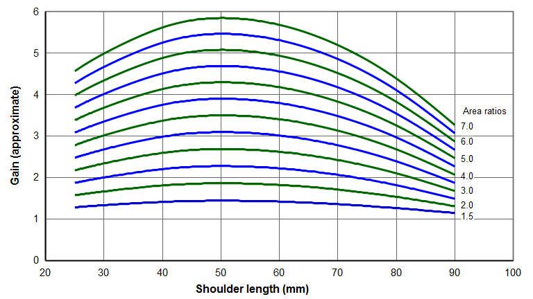
注意,峰值增益出现在肩部长度约为 50 mm 处。在该区域增益曲线相当平坦,因此肩部长度的微小变化不会显著影响增益。还要注意,由于过渡圆角半径的影响,每种设计的最大增益都小于理论增益(面积比)。
示例
假设下列条件已知 —
- 换能器振幅 = 20 微米
- 增幅杆 = 1.5:1
- 所需变幅杆输出 = 150 微米
- 变幅杆形状 = 无槽圆柱形
- 变幅杆输出直径 = 15 mm(按应用要求)
增幅杆的输出振幅(即变幅杆的输入振幅)为 20 微米 * 1.5 = 30 微米。由于变幅杆输出必须为 110 微米,所需的变幅杆增益为 150/30 = 5.0。从上图纵轴上增益 5.0 处开始,水平读取以找出与增益 5.0 相交的曲线点,可以得到表 1 中的组合。知道了可接受的面积比,就可以用公式 \eqref{eq:10506a} 计算输入直径 —
\begin{align} \label{eq:10506a} D_i = D_o \sqrt{Area~ratio} \end{align}
|
||||||||||||||||
|
对于 6.0 的面积比,增益对肩部长度相对不敏感。例如,肩部长度在 45 mm 到 55 mm 之间时,对增益几乎没有影响。即使肩部长度为 40 mm,增益也只下降 4%;肩部长度为 60 mm 时,增益只下降 2%。这意味着,如果需要,可以在不对增益产生不利影响的情况下,通过调整肩部位置来进行一定的调谐。对于 7.0 的面积比,增益对肩部长度更为敏感。
无槽条形变幅杆
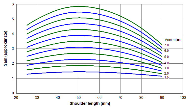
下图适用于无槽阶梯形条形变幅杆。对于不带凸肩(riser)的开槽条形变幅杆也近似适用。(凸肩一般会提高增益。)曲线旁的数值为面积比。
对于条形变幅杆(输入宽度与输出宽度相等),\( Area~ratio \) 就是输入厚度与输出厚度之比。
\begin{align} \label{eq:10505a} Area~ratio &= \frac{T_i} {T_o} \end{align}
其中 —
| \( T_i \) | = 输入段的厚度 |
| \( T_o \) | = 输出段的厚度 |
|
|
|
增幅杆
增幅杆通常通过阳极氧化着色来标示其标称增益。然而,该增益可能只是标称值。以下是几家制造商使用的颜色编码 —
| 颜色 | 增益 |
|---|---|
| 蓝色 | 0.5 |
| 紫色 | 0.6 |
| 绿色 | 1.0 |
| 金色 | 1.5 |
| 银色 | 2.0 |
| 黑色 | 2.5 |
Gain
Contents
Definition
In general (for any system):
\begin{align} \label{eq:10501a} \textsf{Gain} = \frac{\textsf{Output}}{\textsf{Input}} \end{align}
For ultrasonic resonators the gain indicates an amplitude ratio:
\begin{align} \label{eq:10502a} \textsf{Gain} = \frac{\textsf{Output amplitude}}{\textsf{Input amplitude}} \end{align}
or, sometimes, a velocity ratio:
\begin{align} \label{eq:10503a} \textsf{Gain} = \frac{\textsf{Output velocity}}{\textsf{Input velocity}} \end{align}
For a given resonator, equations \eqref{eq:10502a} and \eqref{eq:10503a} give the same value.
Unless otherwise specified:
- All amplitudes are in the primary (desired) directions.
- For an axial resonator the relevant amplitudes are the axial amplitudes.
- For a radial disk resonator the input amplitude may be either radial or axial, depending on the design. The output amplitude is the radial amplitude at the periphery of the disk.
- For a flexure resonator the input amplitude is axial. The output amplitude is the flexure amplitude.
- The output amplitude is measured at the center of the face.
- The input amplitude is measured at the center of the stud surface.
If a resonator is said to have gain but no specific value is mentioned, the gain is assumed to be greater than 1.0 (i.e., forward gain). (If the gain is less than 1.0 then the resonator is said to have reverse gain.)
Theory
For any vibrating system that is not acted upon by external forces, momentum must be conserved. For a simple axial resonator for which any transverse motion can be neglected ...
For a halfwave resonator with a sharp step exactly at the node and for which the input section and output section is each prismatic (constant cross-sectional area) and which is made of a single material, the theoretical gain is just the ratio of the output area to the input area.
\begin{align} \label{eq:10507a} {\textsf{Gain}}_{\textsf{theoretical}} = \textsf{Area ratio} \end{align}
where —
\begin{align} \label{eq:10508a} \textsf{Area ratio} &= \frac{\textsf{Area of input surface}}{\textsf{Area of output surface}} \end{align}
Limitations
The definition of gain only considers amplitudes in the primary directions. Then for an axial resonator the calculated gain doesn't account for transverse motion. However, such transverse motion may be significant to the application. For example, many bell horns have appreciable transverse motion. This motion can be helpful for cavitation or defoaming. However, it can be detrimental for plastic welding since it can cause marking of the part (with associated excessive power consumption) and poor welds. Also, such transverse motion can add significant additional stress. Hence, resonators can't be directly compared based solely on their gains.
Composite horns.
Preference for higher gain horns
For two horns that have the same output areas, it can be shown that the horn with the higher gain will have lower energy storage, despite having more mass. (See appendix zzz.) Thus, for large horns that are difficult to start, a higher gain horn will be preferred.
For a given output amplitude a higher gain horn will require lower input amplitude. This means that the hornbooster joint will have lower stress and will last longer before reconditioning is needed. This also means that a lower gain (lower stress) booster can be used so that perhaps the booster can be made from aluminum instead of titanium.
Measurement
Ti Std horn. Intermediate feedback xdu.
For some horns (e.g., those with face cavities such as bell horns), amplitude measurement at the center of the horn face may not be possible. In other cases, the gain may preferably be specified at another location. For example, if a horn is only designed to weld around the periphery of its face then it would make most sense to measure the output amplitude in this peripheral area, even though the center of the horn face might be available. In such cases, the location of the gain measurement must be specified (e.g., \( G_{periphery} \)).
Effect of frequency
Estimating gains for unslotted stepped horns
The following graphs show the approximate gains for 20 kHz unslotted horns which have a 40 mm transition radius between the input section and output section. The input section and output section is each prismatic. The values adjacent to the curves are the area ratios. As shown by equation \eqref{eq:10507a} these are also the theoretical gains for a horn with a sharp step (no radius) exactly at the node.
These graphs are applicable to typical acoustic materials (those with a wave speed in the vicinity of 5000 m/sec — e.g., aluminum, titanium, steel). These graphs are suitable for preliminary horn designs. However, note that stresses are not considered.
The graphs are suitable for other frequencies as long as the shoulder length and transition radius are suitably scaled.
Unslotted cylindrical horns
For a cylindrical horn, the \( Area~ratio \) is just the ratio of the input to output diameters.
\begin{align} \label{eq:10504a} Area~ratio &= \frac{{D_i}^2} {{D_o}^2} \end{align}
where —
| \( D_i \) | = Diameter of the input section |
| \( D_o \) | = Diameter of the output section |
|
|
|
Note that the peak gain occurs for shoulder lengths of about 50 mm. In this region the gain curves are fairly flat so a small change in the shoulder length will not significantly affect the gain. Also note that the maximum gain for each design is less than the theoretical gain (the area ratios) due to the effect of the transition radius.
Example
Assume that the following are known —
- Transducer amplitude = 20 microns
- Booster = 1.5:1
- Required horn output = 150 microns
- Horn shape = cylindrical unslotted
- Horn output diameter = 15 mm (as required by the application)
The output amplitude from the booster (which is the input amplitude to the horn) is 20 microns * 1.5 = 30 microns. Since the horn output must be 110 microns the required horn gain is 150/30 = 5.0. Starting with a gain of 5.0 on the vertical axis of the above graph and reading across to find the curve points that intersect the 5.0 gain, the combinations of table 1 are possible. Knowing the acceptable area ratios, the input diameters can be calculated from equation \eqref{eq:10504a} —
\begin{align} \label{eq:10506a} D_i = D_o \sqrt{Area~ratio} \end{align}
|
||||||||||||||||
|
For an area ratio of 6.0 the gain is relatively insensitive to the shoulder length. For example, shoulder lengths between 45 mm and 55 mm have almost no effect on the gain. Even for a shoulder length of 40 mm the gain drops only 4%; for a shoulder length of 60 mm the gain drops only 2%. This means that, if needed, some tuning could occur by adjusting the shoulder position with adversely affecting the gain. For an area ratio of 7.0 the gain is more sensitive to the shoulder length.
Unslotted bar horns
The following graph applies to unslotted stepped bar horns. It is also approximately valid for slotted bar horns without risers. (Risers generally increase the gain.) The values adjacent to the curves are the area ratios.
For a bar horn (for which the input and output widths are equal), the \( Area~ratio \) is just the ratio of the input to output thicknesses.
\begin{align} \label{eq:10505a} Area~ratio &= \frac{T_i} {T_o} \end{align}
where —
| \( T_i \) | = Thickness of the input section |
| \( T_o \) | = Thickness of the output section |
|
|
|
Boosters
Boosters are often color coded by anodizing to indicate the nominal gain. However, the gain may only be nominal. The following are used by several manufacturers —
| Color | Gain |
|---|---|
| Blue | 0.5 |
| Purple | 0.6 |
| Green | 1.0 |
| Gold | 1.5 |
| Silver | 2.0 |
| Black | 2.5 |