均匀性 — 改善方法
(初稿)
目录
- 图
- 图 1. 带环形槽的圆柱形变幅杆
- 图 20. 带外张槽的条形变幅杆(Holze)
- 图 25. 带凸台的条形变幅杆(Holze)
- 图 27. 带侧面凸台的条形变幅杆(4 槽)
- 图 30. 带横向孔的条形变幅杆(2 槽)(Scotto)
- 图 32. 带横向孔的条形变幅杆(4 槽)(Scotto)
- 图 40. 不等肩部长度的条形变幅杆(Harris)
- 图 50. 输入端面带附加半波谐振器的条形变幅杆(Elbert)
- 图 60. 输入端面带附加半波谐振器的条形变幅杆(Scotto)
改善端面振幅均匀性有两种基本方法 — 提高低振幅区域的振幅和/或降低高振幅区域的振幅。
对可调性的需求
有限元分析(FEA)常用于优化变幅杆的均匀性。为简单起见,FEA 一般假定材料是各向同性的。然而,铝在一定程度上是正交各向异性的,钛则是中等程度的正交各向异性。因此,加工出来的变幅杆的实际均匀性往往与 FEA 预测的结果不同。
此外,FEA 假定材料性能保持一致。然而,众所周知,钛的性能会因批次不同而变化,甚至在同一块材料内部也会变化(非均质)。
因此,控制均匀性的方法最好允许在变幅杆加工完成后进行一些最终调整。
去除低振幅区域背后的材料
可以去除低振幅区域背后的材料(例如通过底部切削),从而形成法兰。由于法兰材料不再得到良好支撑,它会因自身惯性而 "扑动"。这种扑动使法兰区域相对于高振幅区域的振幅增大。该效应在去除了材料的附近较为局部化。这种方法可以是主要的(如线轴形变幅杆),也可以是次要的(如加在条形变幅杆端部的法兰)。
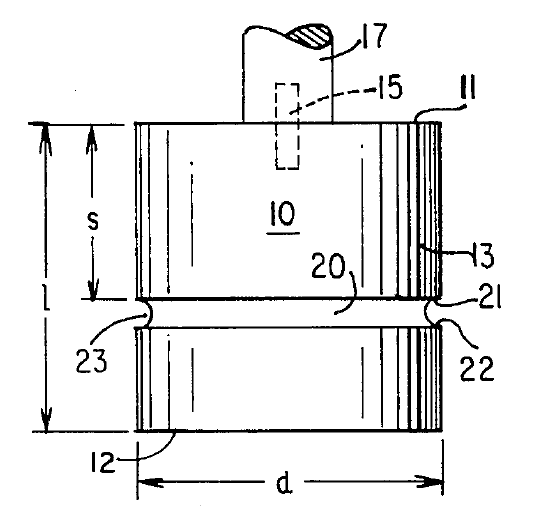
图 1 展示了这种方法:在圆柱形变幅杆上加工出一条环形槽,以提高变幅杆端面外缘处的振幅(Davis[2] 专利 4131505)。槽的位置和尺寸影响变幅杆端面上的振幅分布(图 2)。
重新分配增益
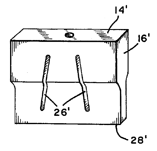
图 20 展示了 Holze 的一项专利,它利用外张槽来重新分配条形变幅杆中的增益。通过使槽向外倾斜,端部单元在波节后方具有更大的质量,在波节前方质量减小,从而增大这些单元的增益。相反,中心单元在波节后方质量减小,在波节前方质量增大,从而减小中心单元的增益。其净效果是外侧端面振幅增大,而中心端面振幅减小。如果槽的角度选择得当,外侧振幅将近乎等于中心振幅 — 即与非外张槽的条形变幅杆相比,均匀性将得到大幅改善。(通常,最佳槽角度相对于螺柱轴线小于 10°。)
遗憾的是,这种设计在加工后没有多少调整余地,因为各单元的相对振幅由固定的槽角度决定。因此,这种设计未被广泛使用。
降低低振幅单元的频率
Culp 利用 2 槽条形变幅杆的弹簧-质量类比模型证明,通过使低振幅单元的频率相对于振幅较高的单元降低,可以提高低振幅单元的振幅。Scotto 也认识到了这一效应。
这主要适用于开槽条形变幅杆,在某种程度上也适用于开槽块形变幅杆。可以通过增加凸台(图 25)、调整波节圆角半径(图 40)、增加波节孔(图 30 和图 32)或对槽进行仿形加工来降低低振幅单元的频率。其次,开槽变幅杆的均匀性还会受到槽参数的影响:横向位置、宽度和槽腹长度。
这些方法的优点在于,它们允许在变幅杆加工完成后调整均匀性。一般做法是选出振幅低的单元,逐渐降低其频率,直到达到最佳均匀性。当然,随着这些单元频率的降低,变幅杆的整体频率也会降低,因此在此过程中需要重新调谐。
凸台(riser)
可以选择性地在变幅杆输入端面上增加附加质量,以降低相应单元的频率。这些质量块在此称为 "凸台"(riser),也曾被称为 "雉堞"(castellation)或 "端部/后部质量块"。(后一种术语并不推荐,因为它们也用于换能器的最后部元件。)
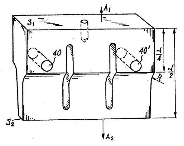
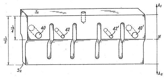
这种方法由 Holze 取得专利;图 25 展示了凸台(实体 36)。Holze 的专利认为,带凸台单元振幅的增大可归因于其增益的增加(由于附加的后部质量)。然而,这一假设是不正确的,因为凸台概念对本身没有增益的无外形变幅杆同样有效。
调整时,凸台初始做得过长,此时单元频率将低于期望值,相应单元的振幅会过高。然后逐渐缩短单元长度(从而提高其频率并降低其振幅),直到达到最佳端面振幅。(注意,整体输出振幅会增大,因为带凸台单元振幅的增大还会通过槽腹的牵拉间接提高相邻无凸台单元的振幅。)
(凸台在恰好覆盖相应单元而不伸入槽区时最为有效。)
凸台很容易用于多槽块形变幅杆,因为它们可以布置在变幅杆的任意单元上方。不过,对振幅的影响通常对外缘单元最大。
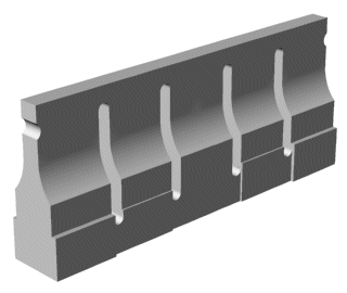
这种设计的一个缺点是后部凸台可能与支撑设备(支架或增幅杆)发生干涉。这可以通过把凸台加在变幅杆侧面而不是后部来解决(图 27)。对单元频率和振幅的影响是相同的。然而,这需要更厚的初始变幅杆材料(材料成本更高,加工成本也增加)。在多槽块形变幅杆上,侧面凸台只能施加于外缘单元,因此只有这些外缘单元的振幅会受到影响。
横向波节孔
波节附近的横向孔可用于降低相应单元的频率(例如图 30 和图 32)。对于这些图中的变幅杆,孔径可以先加工得偏小,然后逐渐扩大,直到达到所需的均匀性。对于这些图中的设计,由于这些成形变幅杆具有增益,孔位于应力相对较低的区域。然而,如果把这些孔用在无外形变幅杆上,则相对应力(在给定输出振幅下)会明显更高。对于多槽块形变幅杆,这些孔可用于调整外侧单元的振幅。(Culp 曾设计了这样一支钛变幅杆,但它最终在波节孔处失效。)
不等肩部长度
变幅杆最初设计或加工成相等的肩部长度(图 40 中的实体 20 和 22)。然后将波节圆角(24)向后加工(减小肩部长度 20),直到达到所需的均匀性。这种设计的缺点是端部单元的波节圆角加工起来有一定难度。对于槽数超过两条的宽条形变幅杆尤其如此。
如前所述,这里的一般原理是降低低振幅单元(本例中为端部单元)的频率,使其振幅相对于高振幅中心单元增大。同样的原理也可应用于交叉开槽的块形变幅杆,即对振幅低的单元进行带束处理。然而,这种带束通常只能在外表面(侧面或端部)上进行,因此带束后的单元在几何上不再对称。
其他方法
人们还提出过其他方法,但由于存在局限性,似乎未被广泛使用。
在变幅杆输入端面上增加附加半波谐振器
图 50 展示了 Elbert 的一项专利,其中圆柱形半波谐振器(16a 和 16b)安装在 2 槽条形变幅杆的输入端面上。(实体 14 是换能器,实体 80a 是波节槽,组件可借助它们得到支撑。)Elbert 没有推测圆柱形谐振器为何能改善变幅杆的端面均匀性。不过,它们很可能是失谐到稍低的频率,因此其作用类似于上面讨论的凸台。此外,这些圆柱形谐振器可能具有一定的横向弯曲运动,可以抵消变幅杆端部单元的低振幅。如果是这样,那么这些圆柱形谐振器的直径可能是一个重要的设计参数,因为直径会影响弯曲运动的大小。
Elbert 的专利(1986 年)似乎与 Scotto[1] 1974 年的法国专利(2203295)非常相似。未能找到 Scotto 专利的详细内容。不过,图 60 展示了来自 Derks[1](第 31 页)的一幅图像。
增加钥匙孔形槽
Cardoni [1] 发现,在常规槽之间增加窄的(钥匙孔形)槽可以显著改善块形变幅杆的均匀性。然而,由此带来的槽应力增加(以及可能缩短的变幅杆寿命)并未被考虑。
块形变幅杆
块形变幅杆在厚度和宽度两个方向上都有槽。上述某些方法也可以应用于块形变幅杆。
Uniformity — methods for improving
(preliminary)
Contents
- Figures
- Figure 1. Cylindrical horn with peripheral groove
- Figure 20. Bar horn with splayed slots (Holze)
- Figure 25. Bar horn with risers (Holze)
- Figure 27. Bar horn (4 slots) with side risers
- Figure 30. Bar horn (2 slots) with transverse holes (Scotto)
- Figure 32. Bar horn (4 slots) with transverse holes (Scotto)
- Figure 40. Bar horn with unequal shoulder lengths (Harris)
- Figure 50. Bar horn with additional half-wave resonators on the input surface (Elbert)
- Figure 60. Bar horn with additional half-wave resonators on the input surface (Scotto)
There are two basic methods for improving face amplitude uniformity — by increasing the amplitude of low amplitude regions and/or decreasing the amplitude of high amplitude regions.
Need for adjustability
FEA is often used to optimize a horn's uniformity. For simplicity, FEA generally assumes that the material is isotropic. However, aluminum is somewhat orthotropic and titanium is moderately orthotropic. Thus, the uniformity of the machined horn will often be different than that predicted by FEA.
In addition, FEA assumes that the material properties remain consistent. However, the properties of titanium are known to vary from lot-to-lot and even within the same piece of material (nonhomogeneous).
Hence, a method for controlling the uniformity should preferably allow for some final adjustments after the horn has been machined.
Remove material behind low-amplitude regions
Material may be removed behind a low-amplitude region (e.g., by undercutting) such that a flange is created. Since the flange material is no longer well supported, it can "flap" due to its inertia. This flapping increases the amplitude in the region of the flange relative to higher-amplitude regions. The effect is somewhat localized near the removed material. This method can be primary (as with spool horns) or secondary (as with flanges added to the ends of bar horns)..
Figure 1 shows this method where a peripheral groove has been machined into a cylindrical horn in order to increase the amplitude at the periphery of the horn's face (Davis[2] patent 4131505). The groove's position and dimensions affect the amplitude distribution across the horn's face (figure 2).
Redistribute the gain
Figure 20 shows a patent by Holze that uses splayed slots to redistribute the gain in a bar horn. By angling the slots outward, the end elements have greater mass behind the node and reduced mass in front of the node, thereby increasing the gain of these elements. Conversely, the center element has reduced mass behind the node and increased mass in front of the node, thereby reducing the gain of the center element. The net effect is that the outboard face amplitude increases while the central face amplitude decreases. If the slot angles are correctly chosen then the outboard amplitude will nearly equal the central amplitude — i.e., the uniformity will be substantially improved compared to a bar horn with non-splayed slots. (Typically the optimum slot angles are less than 10° with respect to the stud axis.)
Unfortunately, this design doesn't allow for much adjustment after machining since the relative element amplitudes are determined by the fixed slot angles. Hence, this design is not widely used.
Reduce the frequency of low-amplitude elements
Using a spring mass analogy for a 2-slotted bar horn, Culp has shown that the amplitudes of low-amplitude elements can be increased by reducing their frequencies relative to elements with higher amplitudes. Scotto also recognized this effect.
This applies mainly to slotted bar horns and somewhat to slotted block horns. The frequency of low-amplitude elements can be reduced by adding risers (figure 25), adjusting the nodal radii (figure 40), adding nodal holes (figures 30 and 32), or contouring the slots. Secondarily, the uniformity of slotted horns will be affected by the slot parameters: lateral locations, widths, and web lengths.
These methods are advantageous because they allow adjustment of the uniformity after the horn has been machined. The general method is to select the elements that have low amplitude and gradually reducing their frequencies until the optimum uniformity has been achieved. Of course, as the frequencies of these elements are reduced, the horn's overall frequency will also be reduced so retuning during this process would be needed.
Risers
Additional mass can be selectively added to a horn's input surface to reduce the frequencies of the associated elements. These masses are here called "risers" but have also been called "castellations" or "end/rear/back masses". (The latter terms are not preferred since they are also used for the rear-most elements of transducers.)
This method was patented by Holze; figure 25 shows the risers (entities 36). The Holze patent indicated that the increased amplitude of the riser elements could be attributed to their increased gain (due to the additional rear mass). However, this assumption is incorrect since the riser concept also works for unshaped horns which inherently do not have gain.
For adjustment the risers are initially made too long for which the element frequencies will be lower than desired and the associated element amplitudes will be too high. Then the element lengths are gradually reduced (thereby increasing their frequencies and reducing their amplitudes) until the optimum face amplitude is achieved. (Note that the overall output amplitude will increase because the increased amplitude of the riser elements will also indirectly increase the amplitude of the adjacent non-riser elements through the tug of the slot webs.)
(The risers are most effective when they exactly cover the associated element without extending into the slot area.)
Risers are easily used with multi-slotted block horns because they can be positioned over any of the horn's elements. However, the effect on amplitude is generally largest for the peripheral elements.
One disadvantage of this design is that the back risers may interfere with the supporting equipment (either the stand or the booster). This can be handled by adding the risers to the sides of the horn rather than at the back (figure 27). The effects on element frequencies and amplitudes are the same. However, this requires thicker initial horn material (higher material cost plus increased machining cost). On multislotted block horns the side risers can only be applied to peripheral elements so only the amplitudes of these peripheral elements will be affected.
|
|
| Figure 27. Bar horn (4 slots) with side risers |
|
Lateral nodal holes
Lateral holes near a node can be used to decrease the frequencies of the associated elements (e.g., figures 30 and 32). For the horns of these figures, the hole diameters can initially be machined undersized and then increased until the desired uniformity has been achieved. For the designs of these figures, the holes are located in areas of relatively low stress because of the gain of these shaped horns. However, if these holes are used in unshaped horns then the relative stress (for a given output amplitude) is significantly higher. For multi-slotted block horns the holes can be used to adjust the amplitudes of outer elements. (Culp designed such a titanium horn but it ultimately failed at the nodal hole.)
Unequal shoulder lengths
The horn is initially designed or machined with equal shoulder lengths (entities 20 and 22 in figure 40). The nodal radii (24) are then machined back (reducing the shoulder lengths 20) until the desired uniformity has been achieved. The disadvantage of this design is that the nodal radii of the end elements are somewhat difficult to machine. This is especially true of wide bar horns that have more than two slots.
As discussed, the general principle here is to reduce the frequency of the low-amplitude elements (in this case, the end elements) to that their amplitude increases relative to the high amplitude center element. The same principle can be applied to cross-slotted block horns by banding the elements that have low amplitude. However, such banding can typically only be done on external surfaces (sides or ends) so the banded element is no longer geometrically symmetric.
Other methods
Other methods have been proposed but do not seem to have been widely used because of limitations.
Add additional half-wave resonators on the horn's input surface
Figure 50 shows a patent by Elbert where cylindrical half-wave resonators (16a and 16b) are attached to the input surface of the two-slotted bar horn. (Entity 14 is the transducer and entities 80a are nodal grooves by which the assembly can be supported.) Elbert doesn't speculate on the reason why the cylindrical resonators improve the face uniformity of the horn. However, it seems likely that they are detuned to a somewhat lower frequency so their effect is similar to the risers that were discussed above. In addition, these cylindrical resonators may have some lateral flexural motion that counteracts the low amplitude of the horn's end elements. If so, then the diameters of these cylindrical resonators may be an important design parameter since these diameters affect the amount of flexure motion.
Elbert's patent (1986) seems to be very similar to Scotto's[1] 1974 French patent (2203295). The details of Scotto's patent could not be found. However, figure 60 shows an image from Derks[1] (p. 31).
Add keyhole slots
Cardoni [1] found that adding narrow (keyhole) slots between the conventional slots could considerably improve the uniformity of block horns. However, the consequential increase in slot stress (and possible reduction in horn life) was not considered.
Block horns
Block horns have slots in both the thickness and width directions. Some of the above methods can also be applied to block horns.
![图 25. 条形变幅杆凸台(Holze[3] 专利 4363992)](_images/holze_patent_4363992__fig4__10b.png)
![图 40. 不等肩部长度的条形变幅杆(Harris[1] 专利 4651043)](_images/harris_patent_4651043__fig1__10d.png)
![图 50. 输入端面带附加半波谐振器的条形变幅杆(Elbert[1] 专利 4607185)](_images/elbert_patent_4607185__fig1__10c.png)
![图 60. 输入端面带附加半波谐振器的条形变幅杆(Scotto[1] 专利 2203295)](_images/scotto_patent_2203295__10b.png)