线轴形变幅杆 — 建设中
目录
- 图
- 图 1a. 标准线轴形变幅杆
- 图 10. 可实现的端面均匀性
- 图 20. 20 kHz Al 7075-T6 无槽圆柱形变幅杆的调谐长度
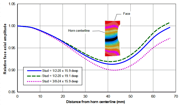
- 图 30. 钢螺柱对 20 kHz Al 7075-T6 Ø135 线轴形变幅杆端面振幅的影响
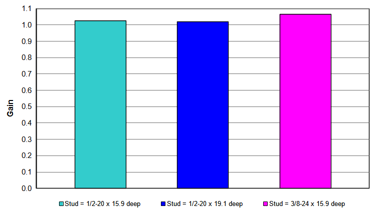
- 图 31. 钢螺柱对 20 kHz Al 7075-T6 Ø135 线轴形变幅杆增益的影响
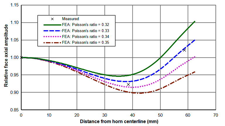
- 图 40. 泊松比对 20 kHz Al 7075-T6 Ø125 线轴形变幅杆端面振幅的影响
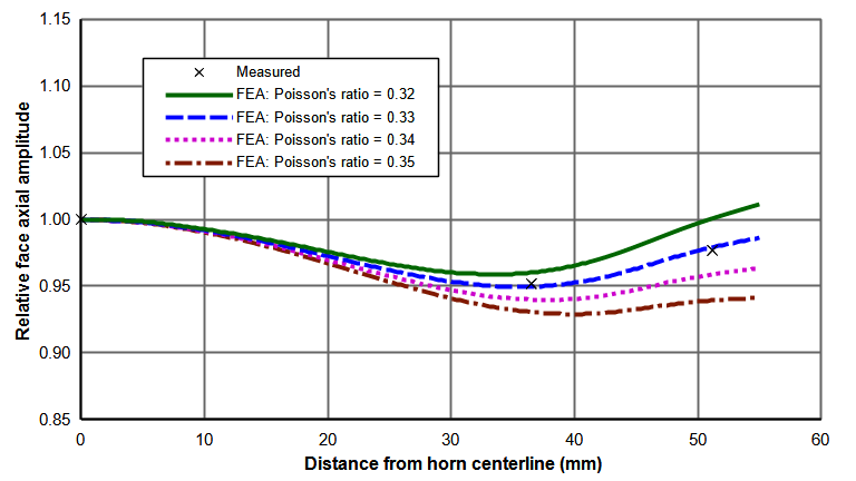
- 图 41. 泊松比对 20 kHz Al 7075-T6 Ø110 线轴形变幅杆端面振幅的影响
下文讨论改善大直径无槽圆柱形变幅杆均匀性的步骤。
除非另有说明 —
- 凡提到 "振幅" 和 "均匀性",均指变幅杆端面上的振幅和均匀性。
- 假定变幅杆为平端面(即无端面仿形或型腔)。
- 设计和性能基于 7075-T6 铝,其波速约为 5005 m/sec,泊松比为 0.33。这些结果应大致适用于性能相近的材料(如钛、许多钢种),但为获得最佳性能可能需要做一些调整(尤其是底部切削直径)。然而,波速明显不同的材料(铜合金、AlBeMet)或泊松比明显不同的材料(AlBeMet、某些钢种)必须单独优化。
- 建议的尺寸适用于 20 kHz 变幅杆。这些尺寸可以按比例换算到其他频率。
- 所有尺寸均为近似值,应根据具体变幅杆和/或应用的需要进行调整。
- 所有振幅均以变幅杆端面中心的轴向振幅 1.0 为基准。
无外形圆柱形变幅杆
对于无外形圆柱形变幅杆,泊松耦合使端面振幅在端面中心最高、在外缘最低。(详见此处。)图 1 展示了 Ø135 mm 变幅杆的端面振幅分布。
图 2 展示了端面振幅均匀性随变幅杆直径的变化。对于直径不超过 60 mm 的变幅杆,均匀性大于 0.9(90%)。对于更大的变幅杆,均匀性迅速下降。对于 Ø135 mm 变幅杆,均匀性仅约 0.25。这种不均匀性会在执行应用时造成问题。
图 3 展示了端面外缘处的径向振幅。在 Ø125 mm 以内,径向振幅小于变幅杆端面中心轴向振幅的 2%。超过 Ø130 mm 后,径向振幅迅速增大。在更大的直径下,径向振幅占主导地位,变幅杆的表现更像一个径向振动的圆盘。
线轴形变幅杆
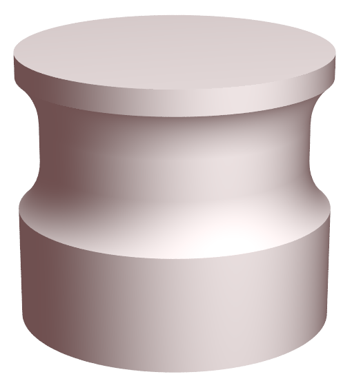
为了改善端面轴向均匀性,在变幅杆端面后方的外周切削出线轴形状(有点像绕线轴)。
线轴形底部切削通过让法兰材料 "扑动",提高端面外缘及邻近区域的振幅。一般来说,当端面外缘处的轴向振幅等于端面中心的振幅时,底部切削达到最佳。在这两个位置之间,振幅会稍低一些,因为 "扑动" 在该区域没有那么有效。
特性
端面型腔
带有较大端面型腔的线轴形变幅杆(尤其是大直径者)无法保持良好的均匀性。(像用于冷却或抽真空的轴向小孔这样的小型腔或许可以接受。)如果需要较大的端面型腔,则应改用开槽圆柱形变幅杆。
最大直径
在 20 kHz 下,合理的最大变幅杆直径约为 135 mm。这一限制来自振幅均匀性、径向振幅以及相邻非轴向谐振三方面的要求。
振幅均匀性
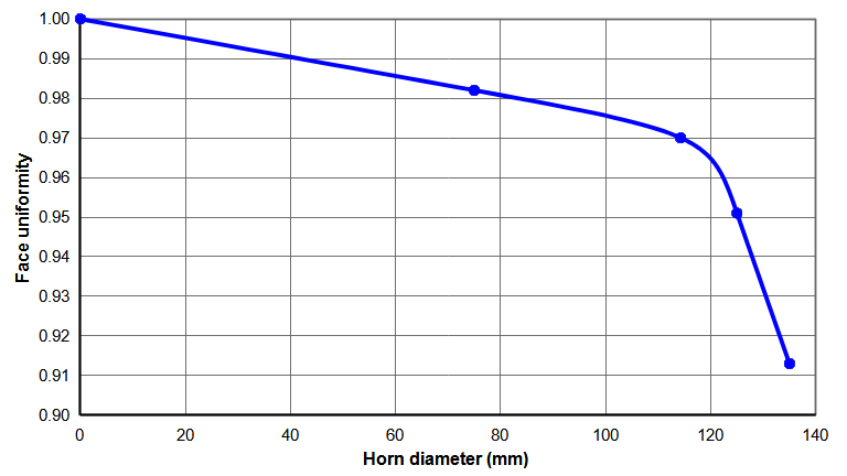
图 10 展示了按图 4 设计的线轴形变幅杆所能实现的端面均匀性。对于直径超过约 Ø120 mm 的变幅杆,可实现的端面均匀性急剧下降。
径向振幅
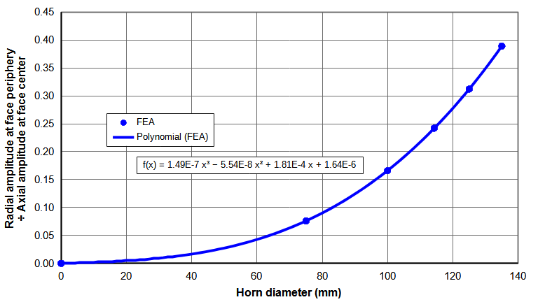
在 Ø 135 mm 时,径向振幅约为轴向振幅的 39%;超过该直径后,径向振幅迅速增大(图 6),这可能影响应用(例如擦伤塑料件)。该径向振幅之所以高,是因为底部切削使端面表现得像一个径向振动的圆盘。
相邻的非轴向谐振
在 Ø135 mm 以上存在一个对称的非轴向谐振,可能对轴向谐振产生不利影响。图 7 展示了 Ø135 mm 线轴形变幅杆在 21213 Hz 处的这一模态。
排除的直径
直径接近 100 mm 的变幅杆在 20 kHz 附近存在一个非对称剪切谐振。该谐振在端面和螺柱表面上具有一条直径方向的波节线(图 8 和图 9)。当这个非对称谐振接近轴向谐振时,会导致端面和螺柱表面上的振幅不对称。直径小于 90 mm 或大于 110 mm 的线轴形变幅杆似乎相对不受该谐振影响;直径介于两者之间的线轴形变幅杆必须仔细评估,以确保任何非对称端面振幅不会影响应用或引起其他问题(例如变幅杆-增幅杆接头发热或换能器发热)。
增益
线轴形变幅杆的增益接近 1.0,尽管底部切削(波节前方质量减小)似乎意味着更高的增益。增益随变幅杆直径增大而降低(图 11)。(注:按惯例,增益在变幅杆端面中心处测量。)
应力
最高应力出现在波节附近的底部切削圆角处。直径不超过 Ø135 mm 的所有 Al 7075‑T6 线轴形变幅杆,其应力范围为每微米峰值输出振幅 2.34 – 2.48 MPa [340 – 360 psi]。这些变幅杆在 25 微米峰值输出振幅(59 - 62 MPa)下已被证明是可靠的。由于 Al 7075-T6 的疲劳强度为 130 - 140 MPa,这些线轴形变幅杆很可能在明显更高的振幅下也能可靠工作。
设计步骤
参考下图 —
|
|
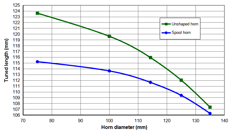
| 图 20. 20 kHz Al 7075-T6 无槽圆柱形变幅杆的调谐长度 |
|
- 选择变幅杆材料。
- 如果可能,使用铝(如 Al 7075‑T6),它相对便宜且易于加工。如有需要,可以通过端面镀层(如镀硬铬)提高耐磨性。(注意:某些镀层会降低疲劳寿命。)
- 当铝无法解决磨损或冲击问题时,可使用钛(如 Ti-6Al-4V)。
铝线轴形变幅杆的疲劳失效很少见,因此钛相对于铝的疲劳优势通常不在考虑之列。
注意,大直径钛线轴形变幅杆可能难以由电源启动,尤其是在用高增益增幅杆驱动时。功耗也会很高。例如,一支输出约 45 微米的 Ø135 mm 钛线轴形变幅杆在空气中的功耗超过 400 瓦(Culp[0])。因此,不推荐使用大直径钛线轴形变幅杆。
- 确定尺寸。
- 法兰长度。12 mm 的法兰效果良好。更大的法兰会使端面振幅最低点更靠近中心线,并能略微提高均匀性。然而,底部切削必须更深以作补偿,从而导致更高的应力。
- 底部切削圆角半径。25 mm 的圆角半径效果良好。更小的圆角半径会提高端面外缘处的振幅。但此时底部切削直径必须减小,从而导致均匀性有所下降。
- 底部切削直径。使底部切削直径约为变幅杆直径的 85.5%。对所有变幅杆尺寸而言,这都能给出近似最佳的端面均匀性。(可能需要做一些调整,以补偿螺柱(见下文)和材料的影响。为稳妥起见,先做较浅的底部切削,然后减小底部切削直径,以获得最佳结果。大直径变幅杆对底部切削直径非常敏感(即该直径的微小变化会显著影响端面均匀性)。例如,对于 Ø135 mm 线轴形变幅杆,将底部切削直径从 86.0% 减小到 85.3%,会使边缘轴向振幅从中心轴向振幅的 86% 提高到 101%。这种敏感性还会因泊松比(见下文)的影响而加剧。)
- 后肩位置。后肩是后部圆角与后部大径相交处。将变幅杆端面到肩部的距离设为无外形圆柱形变幅杆调谐长度的 57%(见图 20)。这给出最高的增益(尽管增益受肩部位置的影响不大)。
- 螺柱。在螺柱直径约 13 mm 以内,端面振幅和增益受螺柱尺寸的影响不大。例如,参见 Ø135 mm 线轴形变幅杆的图 30 和图 31。更小的线轴形变幅杆受影响更小。(振幅还会受螺柱材料的影响 — 钢与钛之别。)
|
|
图 30. 钢螺柱对端面振幅的影响
(20 kHz Al 7075-T6 Ø135 线轴形变幅杆) |
|
|
|
| 图 31. 钢螺柱对 20 kHz Al 7075-T6 Ø135 线轴形变幅杆增益的影响 |
|
- 调谐长度。采用图 4 的尺寸时,调谐长度如图 20所示。由于法兰长度固定,变幅杆必须从螺柱端面一侧进行调谐。对所有变幅杆而言,在连接换能器的情况下,调谐速率约为 120 Hz/mm。(线轴形变幅杆的调谐长度总是比同直径的无外形变幅杆短。因此,图 20 的预调谐长度可以直接设为同直径无外形变幅杆的长度。)
泊松比的影响
在用 FEA 设计线轴形变幅杆时,泊松比的取值会对变幅杆端面上得到的振幅分布产生显著影响。图 40 展示了 Ø125 mm Al 7075‑T6 线轴形变幅杆的这一效应。当泊松比从 0.32 变化到 0.35 时,外缘处的振幅变化约 15%。这一效应随变幅杆直径减小而减弱,如图 41 中 Ø110 mm Al 7075‑T6 线轴形变幅杆所示,在最低与最高泊松比之间,外缘处振幅变化约 7%。详见……
|
|
图 40. 泊松比对端面振幅的影响
(20 kHz Al 7075-T6 Ø125 线轴形变幅杆) |
|
|
|
图 41. 泊松比对端面振幅的影响
(20 kHz Al 7075-T6 Ø110 线轴形变幅杆) |
|
Spool Horns - Under Construction
Contents
- Figures
- Figure 1a. Standard spool horn
- Figure 10. Achievable face uniformity
- Figure 20. Tuned lengths for 20kHz Al 7075-T6 unslotted cylindrical horns
- Figure 30. Effect of steel stud on face amplitudes for 20kHz Al 7075-T6 Ø135 spool horn
- Figure 31. Effect of steel stud on gain for 20kHz Al 7075-T6 Ø135 spool horn
- Figure 40. Effect of Poisson's ratio on face amplitudes for 20kHz Al 7075-T6 Ø125 spool horn
- Figure 41. Effect of Poisson's ratio on face amplitudes for 20kHz Al 7075-T6 Ø110 spool horn
The following discusses the procedure for improving the uniformity of large diameter unslotted cylindrical horns.
Unless otherwise specified —
- References to "amplitude" and "uniformity" will mean those on the horn’s face.
- Horns are assumed to be flat faced (i.e., no face contour or cavity).
- The designs and performances are based on 7075-T6 aluminum with a wave speed of approximately 5005 m/sec and a Poisson's ratio of 0.33. These should apply approximately to materials with similar properties (e.g., titanium, many steels) but some adjustments (particularly the undercut diameter) may be needed for optimum performance. However, materials with significantly different wave speeds (copper alloys, AlBeMet) or significantly different Poisson's ratios (AlBeMet, some steels) must be optimized separately.
- The suggested dimensions apply to 20 kHz horns. These dimensions can be scaled to other frequencies.
- All dimensions are approximate and should be adjusted as needed for the particular horn and/or application.
- All amplitudes are referenced to 1.0 axial at the center of the horn face.
Unshaped cylindrical horns
For unshaped cylindrical horns, Poisson's coupling gives a face amplitude that is highest at the center of the face and lowest at the periphery. (See details.) Figure 1 shows the face amplitude distribution for a Ø135 mm horn.
Figure 2 shows how the face amplitude uniformity varies with the horn diameter. For horns with diameters up to 60 mm the uniformity is greater than 0.9 (90%). For larger horns the uniformity falls off quickly. For a Ø135 mm horn the uniformity is only about 0.25. Such nonuniformity can cause problems in performing the application.
Figure 3 shows the radial amplitude at the face periphery. Up to Ø125 mm the radial amplitude is less than 2% of the axial amplitude at the center of the horn's face. Above Ø130 mm the radial amplitude increases quickly. At even larger diameters the radial amplitude predominates and the horn acts more like a radially vibrating disk.
Spool horns
In order to improve the face axial uniformity, a spool shape (somewhat like a spool of thread) is cut into the periphery of the horn behind the face.
|
|
| Figure 1. Standard spool horn |
|
The spool undercut increases the amplitude at the face periphery and in areas adjacent to the periphery by allowing the flange material to "flap". Generally, the optimum undercut is achieved when the axial amplitude at the face periphery equals the amplitude at the center of the face. In between these two locations the amplitude will be somewhat lower because the "flapping" is not as effective in this region.
Characteristics
Face cavity
Spool horns (especially the larger diameters) with a substantial face cavity do not retain good uniformity. (A small cavity like an axial hole for cooling or vacuum may be acceptable.) If a substantial face cavity is required then a slotted cylindrical horn should be used instead.
Maximum diameter
The largest reasonable horn diameter is about 135 mm at 20 kHz. This is limited by requirements for amplitude uniformity, radial amplitude, and an adjacent nonaxial resonance.
Amplitude uniformity
Figure 10 shows the achievable face uniformity for spool horns that are designed according to figure 4. The achievable face uniformity decreases sharply for horns above about Ø120 mm.
|
|
| Figure 10. Achievable face uniformity |
|
Radial amplitude
At Ø 135mm the radial amplitude is about 39% of the axial amplitude; above this diameter the radial amplitude increases quickly (figure 6), which may affect the application (e.g., scuffing of the plastic part). This radial amplitude is high because the undercut makes the face appear like a radially vibrating disk.
|
|
| Figure 6. Standard spool horn |
|
Adjacent nonaxial resonance
Above Ø135 mm there is a symmetric nonaxial resonance that can adversely affect the axial resonance. Figure 7 shows this mode at 21213 Hz for a Ø135 mm spool horn.
Excluded diameters
Horns with diameters near 100 mm have an asymmetric shear resonance near 20 kHz. This resonance has a diametral node across the face and stud surface (figures 8 and 9). When this asymmetric resonance is close to the axial resonance it causes asymmetric amplitudes on the face and stud surfaces. Spool horns with diameters less than 90 mm or greater than 110 mm appear to be relatively unaffected by this resonance; spool horns between these diameters must be carefully evaluated to make sure that any asymmetric face amplitudes will not affect the application or cause other problems (e.g., heating of the horn-booster joint or heating of the transducer).
Gain
Spool horns have a gain near 1.0, even though the undercut (reduced mass forward of the node) would seem to indicate a higher gain. The gain decreases as the horn diameter increases (figure 11). (Note: as is common practice, the gain is measured at the center of the horn's face.)
Stress
The highest stress occurs in the undercut radius that is near the node. The stress for all of the Al 7075‑T6 spool horns up to Ø135 mm ranges from 2.34 – 2.48 MPa/micron_peak output [340 – 360 psi]. These horns have proven reliable at output amplitudes of 25 microns_peak (59 - 62 MPa). Since Al 7075-T6 has a fatigue strength of 130 - 140 MPa, it is likely that these spool horns would be reliable at significantly higher amplitudes.
Design procedure
Refer to the following —
|
|
| Figure 20. Tuned lengths for 20kHz Al 7075-T6 unslotted cylindrical horns |
|
- Choose the horn material.
- If possible, use aluminum (e.g., Al 7075‑T6) which is relatively inexpensive and is easy to machine. If needed, wear resistance can be improved by plating the face (e.g., hard chrome). (Caution: some platings can reduce fatigue life.)
- Titanium (e.g., Ti-6Al-4V) can be used where wear or impact problems can't be resolved with aluminum.
Fatigue failures of aluminum spool horns are rare so the fatigue advantage of titanium over aluminum is usually not a consideration.
Note that large diameter titanium spool horns may be difficult for the power supply to start, especially when driven with a high gain booster. Power consumption will also be high. For example, a Ø135 mm titanium spool horn with approximately 45 microns output draws in excess of 400 watts in air (Culp[0]). Thus, large diameter titanium spool horns are not recommended.
- Specify the dimensions.
- Flange length. A 12 mm flange works well. A larger flange will shift the point of lowest face amplitude closer to the centerline and can increase the uniformity slightly. However, the undercut will have to be deeper to compensate, resulting in higher stress.
- Undercut radius. A 25 mm radius works well. A smaller radius will increase the amplitude at the face periphery. Then the undercut diameter will have to be reduced, resulting in somewhat lower uniformity.
- Undercut diameter. Make the undercut diameter approximately 85.5% of the horn diameter. For all horn sizes this will give approximately the best face uniformity. (Some adjustment may be needed to compensate for the stud (below) and the material. To be safe, start with a shallower undercut and then reduce the undercut diameter in order to achieve the optimum result. Large diameter horns are very sensitive to the undercut diameter (i.e., small changes in this diameter will significantly affect the face uniformity). For example, for a Ø135 mm spool horn, reducing the undercut diameter from 86.0% to 85.3% increases the edge axial amplitude from 86% to 101% of the center axial amplitude. This sensitivity is compounded by the effect of Poisson's ratio (below).
- Rear shoulder location. The rear shoulder is where the rear radius intersects the rear major diameter. Set the distance from the horn face to the shoulder as 57% of the tuned length of the unshaped cylindrical horn (see figure 20). This gives the highest gain (although the gain is only somewhat affected by the shoulder location).
- Stud. Up to a stud diameter of approximately 13 mm, the face amplitude and gain are only somewhat affected by the stud dimensions. For example, see figures 30 and 31 for a Ø135 mm spool horn. Smaller spool horns show even less effect. (The amplitudes will also be affected by the stud material — steel versus titanium.)
|
|
Figure 30. Effect of steel stud on face amplitudes
for 20kHz Al 7075-T6 Ø135 spool horns |
|
|
|
| Figure 31. Effect of steel stud on gain for 20kHz Al 7075-T6 Ø135 spool horn |
|
- Tuned length. With the dimensions of figure 4, the tuned lengths are shown in figure 20. Because the flange length is fixed, the horn must be tuned from the stud surface. For all horns, the tuning rate will be about 120 Hz/mm with an attached transducer. (The spool horn will always tune shorter than an unshaped horn of the same diameter. Therefore, the pretuned length of figure 20 can just be set to the length of an unshaped horn of the same diameter.)
Effect of Poisson's ratio
When designing spool horns with FEA, the value of Poisson's ratio can have a significant effect on the resulting amplitude distribution across the horn's face. Figure 40 shows this effect for a Ø125 mm Al 7075‑T6 spool horn. As Poisson's ratio varies from 0.32 to 0.35 the amplitude at the periphery changes by about 15%. This effect decreases as the horn diameter decreases, as shown in figure 41 for a Ø110 mm Al 7075‑T6 spool horn where the amplitude at the periphery varies by about 7% between the lowest and highest Poisson's ratios. Details ...
|
|
Figure 40. Effect of Poisson's ratio on face amplitudes
for 20kHz Al 7075-T6 Ø125 spool horns |
|
|
|
Figure 41. Effect of Poisson's ratio on face amplitudes
for 20kHz Al 7075-T6 Ø110 spool horns |
|