模态相互作用
概述
当两个谐振彼此接近时,它们可能会发生相互作用。这会扭曲主谐振的振幅场,和/或可能导致电源跳变到次要的(寄生)谐振。
示例
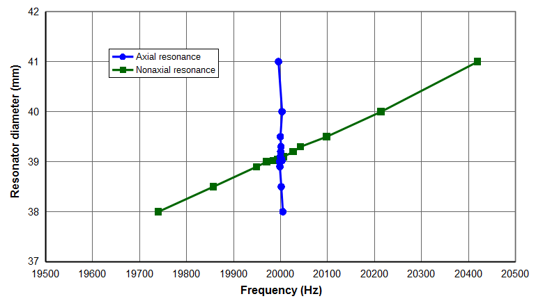
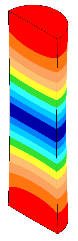
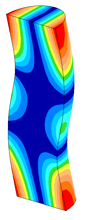
下面给出一个 20 kHz 圆柱形等截面变幅杆(\( c_{tw} \) = 5100 m/sec;泊松比 = 0.33)模态相互作用的示例。变幅杆的直径在 38 mm 到 41 mm 之间调整,以改变模态相互作用的程度。变幅杆的长度做了微小调整(在 126.54 mm 到 126.62 mm 之间),以保持轴向谐振在 20 kHz。正如预期,频率间隔越小,模态相互作用越强。(另见振幅不对称性。)
|
|
| 图 1. 直径 \( \phi \)40 mm 的 20 kHz 变幅杆的频率 |
|
|
|
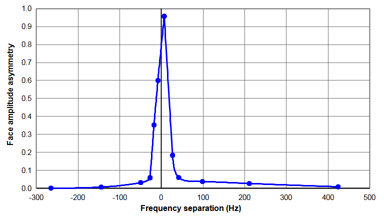
| 图 2. 直径 \( \phi \)40 mm 的 20 kHz 变幅杆的端面振幅不对称性 |
|
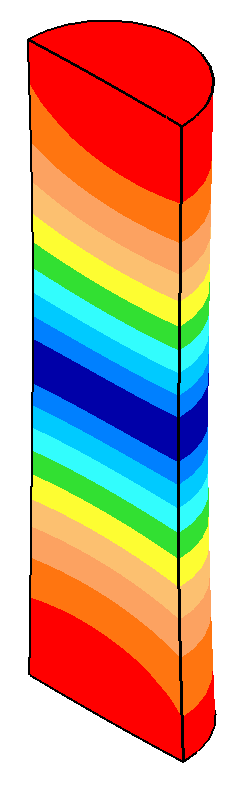
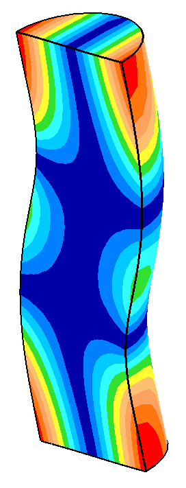
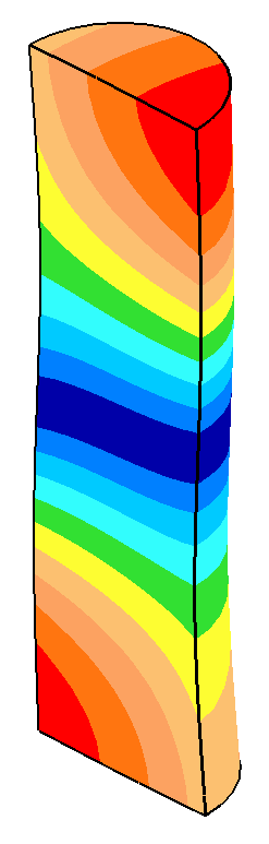
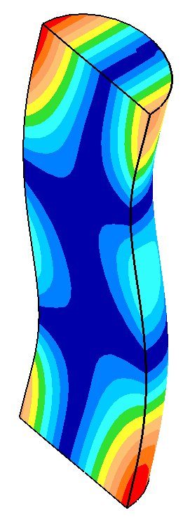
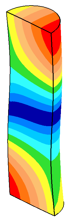
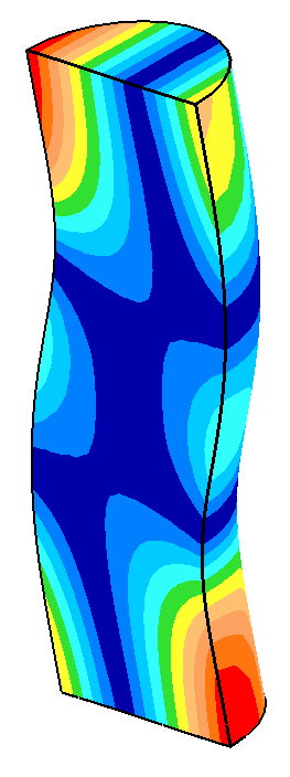
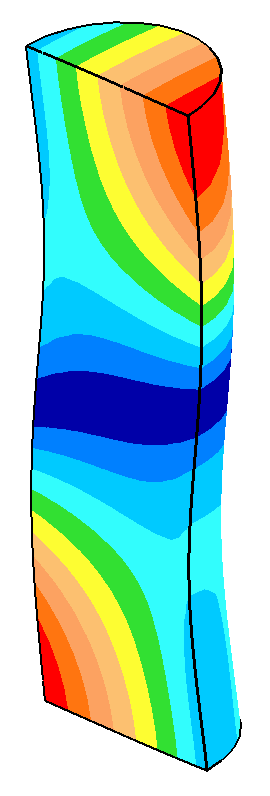
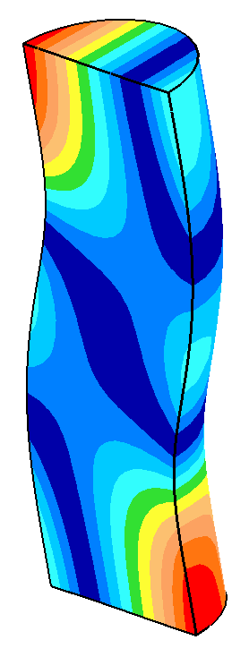
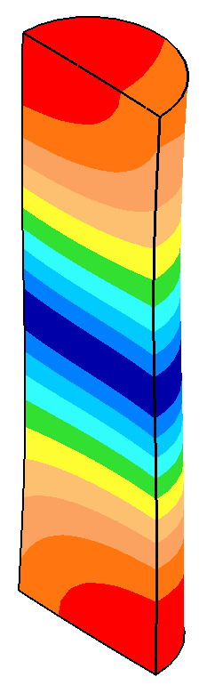
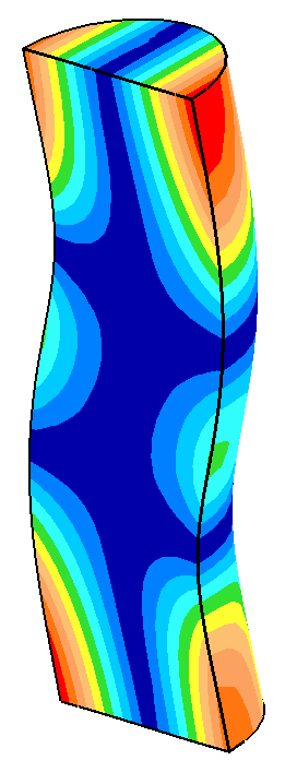
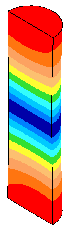
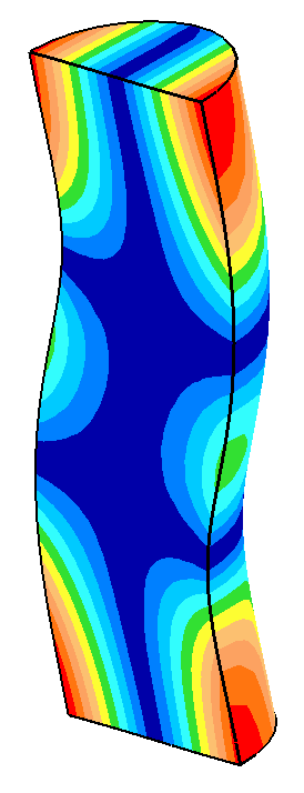
下表给出了上述图中的部分数据。当非轴向(弯曲)模态接近轴向谐振(频率间隔小)时,变幅杆直径的微小变化会引起振幅不对称性的大幅变化。特别是,轴向谐振的端面运动开始呈现弯曲谐振的特征。当频率间隔足够大时,轴向模态的表现就好像弯曲模态不存在一样。
表格说明 —
- 所有位移(以图像颜色表示)均沿轴向。
- 所有位移均以相同比例显示。
| 直径 (mm) |
频率
间隔 (Hz) |
轴向模态 |
非轴向模态 |
| 38.00 |
-265
|
|
|
| 39.00 |
-27 |
|
|
| 39.02 |
-18 |
|
|
| 39.05 |
-12 |
|
|
| 39.10 |
6 |
|
|
| 39.20 |
27 |
|
|
| 39.30 |
42 |
|
|
| 41.00 |
424 |
|
|
建议的频率间隔
在对一个 20 kHz 4.5" x 6"(114 mm x 152 mm)钛合金块形变幅杆的优化中,O'Shea [1](第 260 页)规定轴向与非轴向谐振之间的目标频率间隔至少为 1200 Hz。该目标的原因未作说明。如果其原因是为了避免频率跳变,那么应当指出,自 1991 年该报告发表以来,电源控制技术已有了很大进步,因此更窄的频率范围可能也是可行的。事实上,在 20 kHz 下频率间隔为 500 Hz 的变幅杆已经成功应用。
Liesegang[1A],第 10 页规定在 20 kHz 下频率间隔为 1000 Hz。
Modal interaction
Overview
When two resonances are close together they may interact. This can distort the amplitude field of the primary resonance and/or may cause the power supply to jump to the secondary (parasitic) resonance.
Example
The following shows an example of modal interactions for a 20 kHz cylindrical prismatic horn (\( c_{tw} \) = 5100 m/sec; Poisson's ratio = 0.33). The horn's diamter was adjusted beetween 38 mm and 41 mm in order to affect the amount of modal interaction. The horn's length was adjusted slightly (between 126.54 mm and 126.62 mm) to maintain the axial resonance at 20 kHz. As expected, the modal interaction is greatest when the frequency separation is smallest. (Also see Amplitude asymmetry.)
|
|
| Figure 1. Frequencies for a 20 kHz \( \phi \)40 mm horn |
|
|
|
| Figure 2. Face amplitude asymmetries for a 20 kHz \( \phi \)40 mm horn |
|
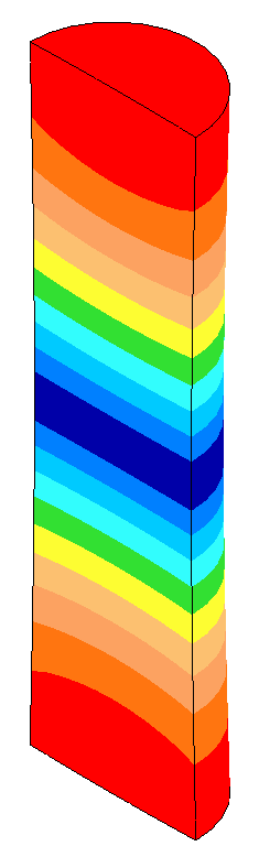
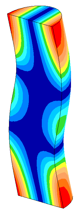
The following table shows some data from the above graphs. When the nonaxial (bending) mode is close to the axial resonance (low frequency separation), small changes in the horn's diameter cause large changes in the amplitude asymmetry. In particular, the face motion of the axial resonance starts to assume characteristics of the bending resonance. When the frequency separation is sufficiently large, the axial mode performs as if the bending mode were not present.
Table notes —
- All displacements (as represented by the image colors) are in the axial direction.
- All displacements are displayed at the same scale.
| Diameter (mm) |
Frequency
separation (Hz) |
Axial mode |
Nonaxial mode |
| 38.00 |
-265
|
|
|
20005 Hz
Asymmetry = 0.001 |
|
|
|
| 39.00 |
-27 |
|
20000 Hz
Asymmetry = 0.06 |
|
|
|
| 39.02 |
-18 |
|
19998 Hz
Asymmetry = 0.34 |
|
|
|
| 39.05 |
-12 |
|
20000 Hz
Asymmetry = 0.50 |
|
|
|
| 39.10 |
6 |
|
20000 Hz
Asymmetry = 0.96 |
|
|
|
| 39.20 |
27 |
|
20000 Hz
Asymmetry = 0.18 |
|
|
|
| 39.30 |
42 |
|
20001 Hz
Asymmetry = 0.06 |
|
|
|
| 41.00 |
424 |
|
|
19996 Hz
Asymmetry = 0.008 |
|
|
|
Suggested frequency separation
In an optimization of a 20 kHz 4.5" x 6" (114 mm x 152 mm) titanium block horn, O'Shea [1] (p. 260) specified a target frequency separation of at least 1200 Hz between the axial and nonaxial resonances. The reason for this target wasn't specified. If the reason was to avoid frequency jump then it should be noted that power supply controls have become much more sophisticated since this 1991 presentation so a narrower frequency range may be possible. In fact, horns having frequency separations of 500 Hz at 20 kHz have been successful.
Liesegang[1A], p.10 specified a frequency separation of 1000 Hz at 20 kHz.