电源
目录
电源是一种电气设备,它将标准的 50 Hz 或 60 Hz 输入电压转换为适合驱动超声换能器的高频输出电压。输出电压的幅值和波形会根据超声应用的要求进行调整。
注 — 本主题讨论电源的一般要求,但不涉及电路的具体细节(调谐电感的要求除外)。
电源的复杂程度
应用的瞬时功率特性可分为四类(通常取决于负载类型),这在一定程度上决定了所需电源的复杂程度 —
- 恒定功率。在整个负载周期内功率保持恒定。当负载相对恒定时会出现这种情况,例如雾化或空化。
- 可变但可预测的功率。功率在整个负载周期内变化,但变化方式可预测 — 即各个负载周期之间的功率变化相同。超声嵌件植入就是一个例子。
- 可变但半可预测的功率。功率在整个负载周期内变化,但变化方式半可预测 — 即总体功率趋势相同,但不同零件之间可能存在一些差异。例如,某些金属焊接零件可能有较厚的氧化层或镀层,需要更长的刮擦时间才能穿透。类似地,某些塑料焊接零件可能有更多的脱模剂。
- 不可预测的功率。功率可以在较大范围内预测,但瞬时功率无法预测。超声骨切割就是一个例子,其骨骼成分随切割深度变化,而且外科医生的操作方式也各不相同(例如,施加力的变化、刀片的扭转或弯曲、润滑量等)。
谐振类型
电源必须指定工作在串联谐振或并联谐振。(在某些情况下也可能指定中间频率。)这两种谐振各有优点,但在实际中都得到广泛应用。无论选择哪一种,换能器都必须与之兼容(即,为串联谐振设计的换能器无法在并联谐振下正常工作,反之亦然)。
主要要求
在某些情况下,宽带功率放大器可能适合驱动超声叠堆。然而,大多数专用超声电源都配备了某些专门的电路/软件,可以获得更好的性能。
自动调谐
锁定主谐振
所有超声系统都有一个主谐振(期望的工作谐振)。此外还会存在次要(寄生)谐振。电源启动时,必须锁定主谐振并忽略次要谐振。
跟踪主谐振
在超声工作过程中,主谐振的频率可能会发生漂移。
- 随着叠堆温度升高(由于内部损耗或负载传递的热量),频率可能向下漂移。
- 由于压电陶瓷的非线性,频率在重功率下可能下降。
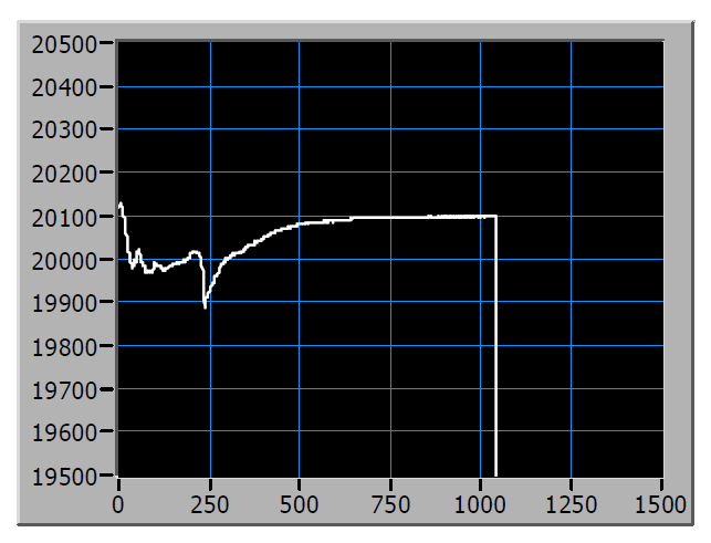
- 频率可能因负载的反作用而漂移。漂移可能是正向的也可能是负向的。例如,图 0 显示了超声金属焊接过程中约 200 Hz 的频率下降(Vlad[1])。
|
|
|
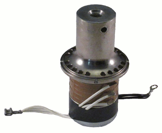
无论原因如何,电源都必须能够自动跟踪这种频率漂移。否则,微小的频率漂移就会导致叠堆输出振幅显著下降。这是因为超声叠堆的带宽通常非常窄。例如,对于图 1 所示的 20 kHz 工业换能器,Culp[0] 通过在驱动源突然断开时测量振幅衰减,确定了约 40 Hz 的开路带宽(即 Q 值约为 500)。在这种情况下,频率只要偏离谐振 20 Hz,就会使换能器的振幅降低 30%,可用输出功率降低 50%(假设电输入恒定)。
当增加其他叠堆部件(增幅杆 + 变幅杆)后,情况会变得更糟(Q 值升高,带宽变窄)。此时频率跟踪变得更加关键。不过要注意,在负载下 Q 值可能会显著下降(即带宽增大),因为能量被传递给了负载。
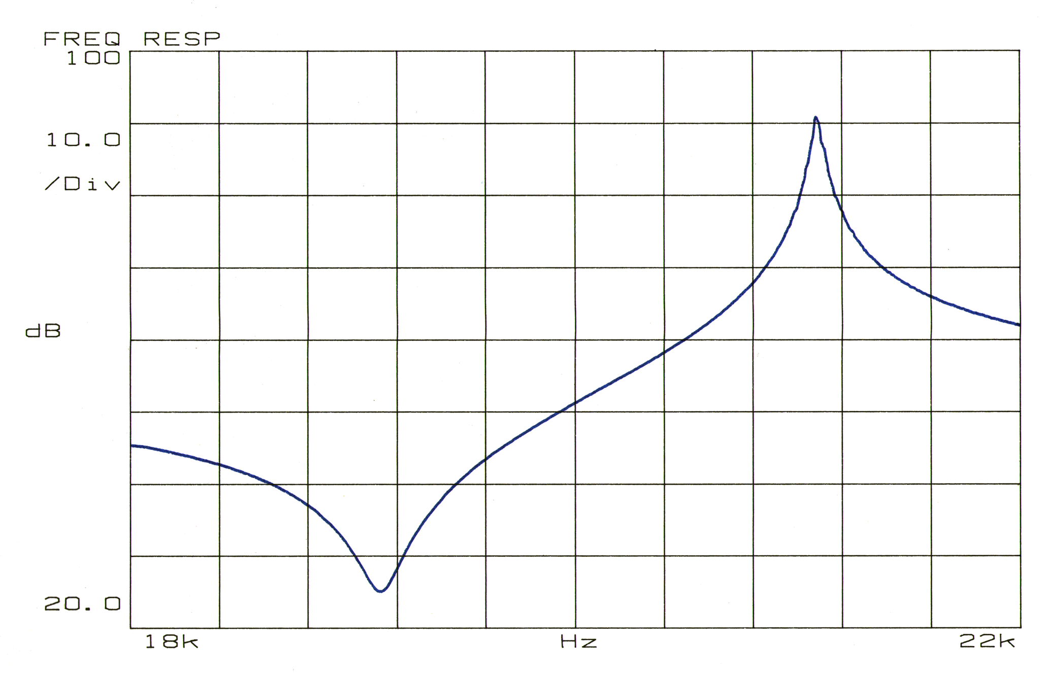
频率跟踪通常由锁相环(PLL)实现,它将电流与电压之间的相位角维持在恒定值。理想情况下,电流和电压应完全同相,使负载呈现纯电阻特性(即没有电抗分量)。然而,在实际中,这对于高 Q(窄带宽)系统可能无法实现,因为频率的微小变化会导致相位的大幅变化。在这样的系统中,PLL 可能难以维持相位。此时,略微失相的工作方式可以让 PLL 获得更好的性能。
|
|
|
|
|
|
振幅自动调节
大多数应用最好通过控制输出振幅而不是功率来控制。原因是功率是力与速度的乘积(其中速度与输出振幅相关)。因此,一个给定的功率可以通过大力小速度、小力大速度或介于两者之间的组合来实现。尽管所有这些条件都能产生相同的功率,但应用可能只对其中一种响应最好。因此,振幅应被视为独立(受控输入)变量,而功率通常应被视为因变(输出结果)变量。
当叠堆在空气中运行(即空载)时,它会具有给定的输出振幅。这就是规格值。然而在负载下,振幅往往会下降。负载越大,振幅下降越明显。这类似于油门位置固定时驾驶的汽车 — 上坡时车速会降低,坡越陡,车速下降越多。
电源需要某种方法来监测叠堆振幅,然后根据需要调节振幅。这类似于汽车的定速巡航,无论坡度多陡,车速都保持恒定。
调谐电感
超声系统的一个特点是,即使负载是纯电阻性的,频率也会随负载漂移。随着负载增大,串联谐振和并联谐振相互靠近。在某个临界负载下,这两个谐振重合。超过临界负载后,系统不再谐振。
为克服这种情况,必须加入调谐电感(见 Waanders,第 10 页)。对于串联谐振工作方式,调谐电感与压电陶瓷并联(即跨接在陶瓷引线上)。对于并联谐振工作方式,调谐电感与压电陶瓷串联(即串接在其中一组陶瓷引线上)— 见 Lin[1]。该电感的阻抗应等于所有压电陶瓷的合成容抗。
次要要求
许多专用超声电源都配有保护系统的电路/软件。这可能包括接地故障保护、功率过载保护、过压保护、过流保护、压电陶瓷温度过高保护以及频率跳变保护(从主谐振跳变到附近的次要谐振)。
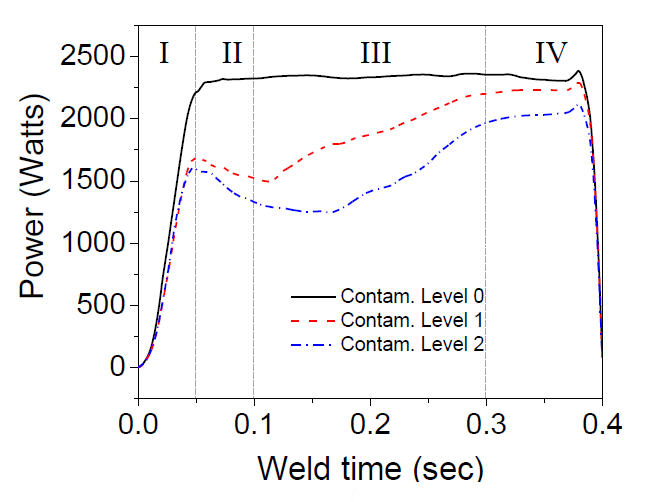
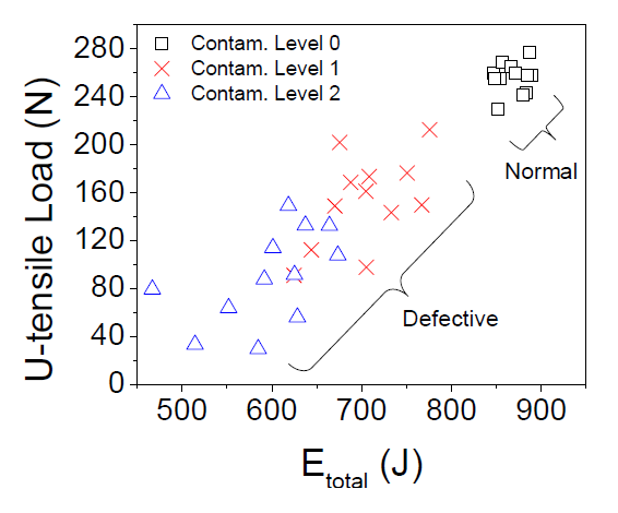
这些电路/软件还可用于监测或控制超声过程。例如,图 3 显示了焊接锂离子电池时不同表面污染水平下的功率曲线(Lee[1],第 70 页)。通过监测能量(图 3 中功率曲线下的面积),可以判定焊缝质量并剔除有缺陷的焊缝(图 4,Lee[1],第 74 页)。此外,还可以控制能量输入,以确保焊缝更加一致,而不受表面污染或其他不可控变量等因素的影响。这一过程被称为"能量控制编程"(energy controlled programming),简称 ECP。对于锂离子电池,Lee 将该最小能量设定为 800 焦耳(第 76 页)。
注 — Lee 焊接的是相对较薄的试片(0.4 mm 焊到 1.0 mm 上(第 19 页),以及 0.2 mm 焊到 1.0 mm 上(第 64 页))。对于具有较大横向尺寸的较厚材料,监测或控制金属焊接过程的能力更加困难。见 de Vries[1],他指出:"因此,人们发现,仅仅了解[金属]焊接系统电输入参数的知识,并不能消除[焊接质量]波动和工具粘住这两个关键问题。"(第 4 页)。不过,塑料焊接系统可能更适合这种监测/控制。
|
|
|
|
另见 — Prokic[1],第 3.0-1 - 3.0-8 页。
Power supplies
Contents
- Figures
- Figure 0. Stack frequency during ultrasonic metal welding
- Figure 1. 20 kHz industrial transducer with six piezoelectric ceramics (33 mode)
- Figure 2. Frequency response impedance plot for a 20 kHz transducer
- Figure 3. Effect of surface contamination on weld power
- Figure 4. Effect of energy input on weld strength
A power supply is an electrical device that converts standard 50 Hz or 60 Hz input voltage into high frequency output voltage that is suitable for driving an ultrasonic transducer. The magnitude and waveform of the output voltage is adjusted to meet the ultrasonic requirements.
Note — This topic discusses the general power supply requirements but not the specifics of the circuitry (except for the requirements of a tuning inductor).
Power supply sophistication
The instantaneour power characteristics of an application fall into four categories (generally depending on the type of load) which, in part, determine the required sophistication of the power supply —
- Constant power. The power is constant for the duration of the load cycle. This occurs when the load is relatively constant such as in atomizing or cavitation.
- Variable but predictable power. The power varies throughout the load cycle but in a predictable manner — i.e., the power variation is the same from one load cycle to the next. Ultrasonic inserting is an example.
- Variable but semi-predictable power. The power varies throughout the load cycle but in a semi-predictable manner — i.e., the general power trend is the same but there may be some variation from part-to-part. For example, some metal welding parts may have thicker oxide or plating layers that require more time to scrub through. Similarly, some plastic welding parts may have more mold release.
- Unpredictable power. The power can be predicted over a large range but instantaneous power can't be predicted. An example is ultrasonic bone cutting where the composition of the bone varies with the cut depth and where the application by the surgeon vaires (e.g., variation in applied force, twisting or bending of the blade, amount of lubrication, etc.).
Resonance type
The power supply must be specified to operate at either series or parallel resonance. (In certain circumstance an intermediate frequency may be specified.) Each of these resonances may have certain advantages but both are widely used in practice. Whichever is chosen, the transducer must be compatible (i.e., a transducer that is designed for series resonance will not operate properly at parallel resonance and vice versa).
Primary requirements
In certain situations a wide band power amplifier might be suitable for driving the ultrasonic stack. However, most dedicated ultrasonic power supplies have certain specialized circuitry/software that allows improved performance.
Auto-tuning
Lock onto the primary resonance
All ultrasonic systems have a primary resonance (the desired operating resonance). In addition there will be secondary (spurious) resonances. When the power supply starts, it must lock onto the primary resonance and ignore the secondary resonances.
Track the primary resonance
During ultrasonic operation the frequency of the primary resonance may shift.
- The frequency may drift lower as the stack temperature increases (either due to internal losses or from heat that is transferred from the load).
- The frequency may drop under heavy power because of nonlinearity of the ceramics.
- The frequency may shift because of reaction to the load. The shift may be either positive or negative. For example, figure 0 shows a frequency drop of approximately 200 Hz during ultrasonic metal welding (Vlad[1]).
|
|
|
Regardless of the cause, the power supply must be able to automatically follow this frequency shift. Otherwise, a small shift in frequency would cause a significant collapse in the stack output amplitude. This is because ultrasonic stacks typically have a very narrow bandwidth. For example, for the 20 kHz industrial transducer shown in figure 1, Culp[0] determined an open-circuit bandwidth of ~40 Hz (i.e., a Q of ~500) from measurements of amplitude decay when the drive source was suddenly disconnected. In this case a frequency shift of just 20 Hz from resonance would reduce the transducer's amplitude by 30% and available power output by 50% (assuming constant electrical input).
When additional stack components (booster + horn) are added, the situation becomes even worse (the Q increases and the bandwidth decreases). Then frequency tracking becomes even more critical. Note, however, that under load the Q may decrease significantly (i.e., the bandwidth increases) as energy is delivered to the load.
Frequency tracking is often handled by a phase lock loop (PLL) where the phase angle between the current and voltage is maintained at a constant value. Ideally the current and voltage would be exactly in phase so that the load would appear to be entirely resistive (i.e., no reactive component). However, in practice this may not be possible in high-Q (narrow bandwidth) system where a small change in frequency results in a large change in phase. In such a system the PLL may have difficulty maintaining the phase. In this case a slightly out-of-phase operation can allow better performance of the PLL.
|
|
|
|
|
|
Auto-adjust amplitude
Most applications can be best controlled by controlling the output amplitude rather than the power. The reason is that the power is the product of force and velocity (where the velocity is related to the output amplitude). Thus, a given power can be achieved by a high force with low velocity or a low force with high velocity or something inbetween. Although all of these conditions can yield the same power, the application may respond best to only one of these. Hence, amplitude should be regarded as the independent (input controlled) variable and power should generally be regarded as the dependent (output resultant) variable.
When the stack runs in air (i.e., unloaded) it will have a given output amplitude. This is the specification. Under load, however, the amplitude tends to collapse. At higher loads the amplitude collapse would be greater. This is analagous to a car that is being driven with a fixed throttle position. The car's speed is reduced on hills — the steeper the hill the greater the speed reduction.
The power supply needs some method of monitoring the stack amplitude and then adjusting the amplitude as required. This is similar to cruise control in a car where the speed is kept constant regardless of the steepness of the hill.
Tuning inductor
A peculiarity of an ultrasonic system is that the frequency will shift under load even if the load is purely resistive. As the load increases the series and parallel resonances move toward each other. At a critical load these two resonances converge. Above the critical load the system is no longer resonant.
To overcome this situation a tuning inductor must be added (see Waanders, p. 10). For operation at series resonance the tuning inductor is added in parallel with the ceramics (i.e., across the ceramic leads). For operation at parallel resonance the tuning inductor is added in series with the ceramics (i.e., in-line with one set of ceramic leads) — see Lin[1]. The impedance of this inductor should equal the combined capacitive impedance of all of the ceramics.
Secondary requirements
Many dedicated ultrasonic power supplies have circuitry/software that protects the system. This can include protection against ground faults, power overloads, over-voltage, over-current, excessive ceramic temperatures, and frequency jumps (a jump from the primary resonance to a nearby secondary resonance).
The circuitry/software may also be used to monitor or control the ultrasonic process. For example, figure 3 shows the power curves for various surface contamination levels when welding lithium-ion batteries (Lee[1], p. 70). By monitoring the energy (the area under the power curves of figure 3) the quality of the welds can be determined and defective welds can be rejected (figure 4, Lee[1], p. 74). Additionally, the energy input can be controlled in order to assure more consistent welds, regardless of factors such as surface contamination or other uncontrolled variables. This process has been called "energy controlled programming" or ECP. For the lithium-ion batteries, Lee sets this minimum energy as 800 joules (p. 76).
Note — Lee welded relatively thin coupons together (0.4 mm welded to 1.0 mm (p. 19) and 0.2 mm welded to 1.0 mm (p. 64)). For thicker materials with significant lateral dimensions, the ability to monitor or control the metal welding process is more difficult. See de Vries[1] who states, "Thus, it has been found that knowledge purely of electrical input parameters to a [metal] welding system do not provide the ability to eliminate the key issues of [weld quality] variability and tool sticking." (p. 4). However, plastic welding systems may be more amenable to such monitoring/control.
|
|
|
|
Also see — Prokic[1], pp. 3.0-1 - 3.0-8.