附录 J:比较 — 短路谐振与开路谐振
换能器通常在短路谐振或开路谐振处(或其附近)工作。(短路谐振也称为串联谐振或简称谐振。开路谐振也称为并联谐振或反谐振。)
振幅
在短路谐振时,阻抗相对较低,因此较小的驱动电压即可激励出较大的振幅。如果驱动电压保持恒定,换能器的振幅将随负载增大而迅速跌落。从这个意义上说,短路谐振类似于串励电机——其转速与负载成反比。
相比之下,开路谐振时的阻抗相对较高,因此需要较大的驱动电压才能激励出合理的振幅。如果驱动电压保持恒定,换能器的振幅随负载增大仅会略有下降(直到中等负载)。从这个意义上说,开路谐振类似于并励电机——无论负载如何,其转速都相对恒定。
损耗
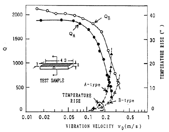
Hirose[1] 研究了单片以 31 模式纵向驱动的压电陶瓷的损耗(Q)。他讨论了陶瓷损耗的成因(第 3 节),并表明(在理论上)反谐振工作(并联谐振)的损耗应低于谐振工作(串联谐振)。第 5 节的实验结果与这一结论一致。在 Hirose 的图 2(即本文图 J1)中,反谐振的品质因数 \( Q_B \) 高于谐振的 \( Q_A \),而反谐振的温升(由损耗引起)低于谐振。请注意,这些结果针对的是长度以 31 模式谐振的单片陶瓷(即电场沿压电陶瓷厚度方向施加,所产生的振动沿压电陶瓷长度方向)。可以推想,对于作为换能器组件一部分的非谐振陶瓷,这些一般性结论仍然成立。
|
|
|
Prokic[1](第 3.2-6 页)对 Branson 20 kHz 换能器进行了功率加载试验。功率先在空气中(装有钟形变幅杆)测量,随后在钟形变幅杆逐渐浸入水中的过程中测量。换能器振幅保持恒定在 20 微米峰峰值。
这些试验表明,在空载条件(即在空气中)直至中等负载下,开路谐振的损耗低于短路谐振。然而,在较大负载下,情况恰好相反。
(应当指出,Branson 的换能器是按开路谐振工作设计的,因此陶瓷厚度和陶瓷片数可能并未针对短路谐振进行优化。例如,由于短路谐振所需的驱动电压较低,可以使用数量更少但更厚的陶瓷而不必担心电弧放电。)
电源方面的考虑
与短路谐振相比,开路谐振的阻抗非常高,因此在给定输出功率下电流通常较低。Mathieson[1](第 56 页)指出:"在开路条件下驱动也被认为是有利的,因为换能器的电流消耗较低,因此在系统设计中可以采用标准的、相对廉价的电源变压器……"
Q
如果设备发生故障而使用户成为接地通路,开路谐振下相对较低的电流可能减轻对用户的伤害。
物理方面的考虑
并联谐振 --> 高电压 ==>
- 陶瓷厚度受最大允许场强限制
- 电弧放电 -
Appendix J: Comparison — short circuit resonance and open circuit resonance
Transducers are typically operated at (or near) either short circuit resonance or open circuit resonance. (Short circuit resonance is also known as series resonance or just resonance. Open circuit resonance is also known as parallel resonance or antiresonance.)
Amplitude
At short circuit resonance the impedance is relatively low so a small drive voltage can induce a large amplitude. If the drive voltage is held constant then the transducer's amplitude will rapidly collapse as the load increases. In this sense a short circuit resonance acts like a series wound motor where the speed is inversely proportional to the load.
In contrast, the impedance at open circuit resonance is relatively high so a large drive voltage is required to induce a reasonable amplitude. If the drive voltage is held constant then the transducer's amplitude will collapse only somewhat as the load increases (up to moderate loads). In this sense an open circuit resonance acts like a parallel wound motor where the speed is relatively constant regardless of the load.
Loss
Hirose[1] considered the loss (Q) of a single piezoelectric ceramic that was driven longitudinally in the 31 mode. He discusses the causes of ceramic loss (section 3) and shows that (theoretically) antiresonant operation (parallel resonance) should have lower loss than resonant operation (series resonance). The experimental results in section 5 agree with this conclusion. In Hirose's figure 2 (figure J1 here), the quality factor \( Q_B \) for antiresonance is higher than \( Q_A \) for resonance, while the temperature rise (due to loss) for antiresonance is lower than for resonance. Note that the results are for a single ceramic that whose length is resonant in the 31 mode (i.e., the electric field is applied across the piezoceramic's thickness and the resulting vibration is along the piezoceramic's length). Presumably, the general conclusions are still valid for a non-resonant ceramic that is part of a transducer assembly.
|
|
|
Prokic[1] (p. 3.2-6) conducted power loading tests on Branson 20 kHz transducers. The power was measured in air with an attached bell horn and then as the bell horn was progressively immersed in water. The transducer amplitude was maintained constant at 20 microns peak-to-peak.
Under no-load conditions (i.e., in air) and up to moderate loading, these tests showed that open circuit resonance has lower loss than short circuit resonance. However, at heavier loading the reverse was true.
(It should be noted that Branson's transducers are designed to operate at open circuit resonance so the ceramic thickness and number of ceramics may not have been optimized for short circuit resonance. For example, since short circuit resonance requires lower drive voltage, fewer but thicker ceramics can be used without concern of electrical arcing.)
Power supply considerations
Compared to short circuit resonance, open circuit resonance has a very high impedance so that the current is typically low for a given power output. Mathieson[1] (p. 56) notes, "Driving under open circuit conditions can also be seen as advantageous, as the current consumption of the transducer is lower and therefore standard and relatively inexpensive power transformers can be utilized in the system design ..."
Q
If a device should malfunction and cause the user to become a ground path, the relatively lower current at open circuit resonance may reduce harm to the user.
Physical considerations
Parallel resonance --> high voltage ==>
- Ceramic thickness is limited by max allowed field strength
- Arcing -