\( Q \)(品质因数)
目录
- 表格
- 表 1. 各种材料的 \( Q \)
概述
\( Q \)(品质因数)是将总储存能量与耗散能量(损耗)相关联的一个属性 —
\begin{align} \label{eq:13601a} Q = 2\pi \left[ \frac{\textsf{Energy stored}}{\textsf{Energy dissipated per cycle}} \right] \end{align}
"每周期的耗散能量"是指为维持固定振荡量所需的外部能量(功)。
如果将分子和分母同乘以频率 \( f \)(周/秒),分母即变为"每秒耗散的能量"(即功率),因此上式也可写成 —
\begin{align} \label{eq:13602a} Q = 2\pi \, f \left[ \frac{\textsf{Energy stored}}{\textsf{Power}} \right] \end{align}
\( Q \) 没有单位。
对于任何系统(电系统、机械系统等)或系统中的任何单个组件或部分,都可以确定其 \( Q \)。注意,对于"理想"系统(即无能量耗散),\( Q \) 为无穷大。
释义
谐振系统
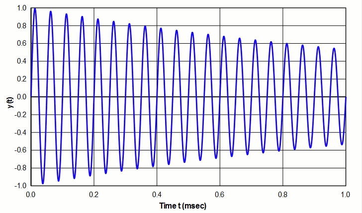
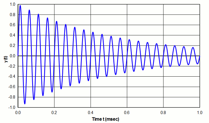
对于自由振荡的谐振系统,\( Q \) 表示振荡因能量损耗而衰减的速率。高 \( Q \) 表示衰减相对缓慢(如图 1 所示),而低 \( Q \) 表示衰减相对迅速(如图 2 所示——参见对数减缩)。
|
|
|
|
|
|
在超声系统中,能量损耗可能来自振动材料内部的摩擦(表现为温度升高)、传递到支撑结构或空气中的能量,或传递到负载的能量。此外,换能器还会因电流流过而产生电(电阻)损耗。
非谐振系统
虽然 Q 常用于谐振系统,但这并非必需。事实上,公式 \eqref{eq:13601a} 和 \eqref{eq:13602a} 同样适用于非谐振系统——特别是电容器和电感器。
一个非理想电容器(即有损耗的电容器)可以表示为理想电容 \( C \) 与电阻 \( R_C \) 的串联。
对于电容器 —
\begin{align} \label{eq:13603a} Q &= \frac{R_C}{(1/2\pi \, f \, C)} \\[0.7em]%eqn_interline_spacing &= R \, (2\pi \, f \, C) \nonumber \end{align}
对于电感器 —
\begin{align} \label{eq:13604a} Q &= \frac{R_L}{(2\pi \, f \, L)} \end{align}
式中 —
| \( R_C \) | = 电容器的等效电阻 |
| \( R_L \) | = 电感器的等效电阻 |
| \( C \) | = 电容 |
| \( L \) | = 电感 |
| \( f \) | = 频率 |
错误的理解
如果已知材料的 \( Q \),则由公式 \eqref{eq:13602a} —
如果已知材料的 \( Q \),并且储存能量(无论是势能(即应变能)还是动能)可以确定或计算出来,那么谐振器理论上耗散的功率就可以由公式 \eqref{eq:13602a} 计算 —
\begin{align} \label{eq:13605a} \textsf{Power} = 2\pi \, f \left[ \frac{\textsf{Energy stored}}{Q} \right] \end{align}
注意,虽然 \( Q \) 与功率损耗相关,但它并不是实际的功率损耗,因为 \( Q \) 还取决于储能。例如,考虑两个完全相同的变幅杆,一个由钛制成,另一个由热处理钢制成。假设两种材料具有相同的 \( Q \),那么这两个相同的变幅杆也将具有相同的 \( Q \)。(在适当的条件下这确实可以实现。)人们可能忍不住会说,由于两个变幅杆具有相同的 \( Q \),因此它们的损耗也相同。然而,钢的密度比钛大 1.5 倍,弹性模量也比钛大 1.5 倍。因此,其储存能量将比钛大 1.5 倍,由公式 \eqref{eq:13605a} 可知其损耗也将大 1.5 倍。
Q 与频率的关系
对于谐振器材料,\( Q \) 与频率之间的关系尚未精确确立。在 Mason 对 Ti-6Al-4V 的测试中,他发现 Q 在高达 XXX MHz 的范围内与频率无关(图 X)。另一方面,ZZZ 发现铝的 \( Q \) 随频率升高而有所下降(图 Y)。不过,可以合理地假设 \( Q \) 在有限的频率范围内大致保持恒定。
Q 与测试条件的关系
\( Q \) 可能取决于以下测试条件 —
加载方式
正如材料可以用两个弹性模量(弹性模量和刚性模量)来表征、且这两个模量取决于材料的加载方式一样, \( Q \) 也可能取决于加载方式。因此,在评估 \( Q \) 的测试数据时,可能需要确定测试是拉伸(最有可能)还是剪切方式。对于材料承受轴向载荷或弯曲载荷的情况,微元会发生体积变化。另一方面,在剪切载荷(如扭转)下,微元不会发生体积变化。(Fine[1A] 第 60 页)因此,有理由质疑在这些情况下耗散机理和耗散程度是否相同。
正如 Bedford[1A] 第 2 页所指出的 —
耗散机理尚未得到很好的理解,但下面的说法大概是正确的:\( Q \) 不仅取决于材料,还取决于几何构型和振动模式。\( Q \) 定义为储存能量与每周期耗散能量之比。储存能量显然通过等效质量和柔度参数而取决于构型和振动模式。当模式和构型改变时,耗散能量似乎不太可能以恰好保持 \( Q \) 不变的方式变化。
Zemanek[1C](第 1285 页)评论说,弯曲谐振比纵向谐振的阻尼更大。然而,尚不清楚他是指这是弯曲模态的固有特性,还是由于他激励弯曲模态的方式所致。
材料的热处理
工具钢淬火后通常损耗(功率)显著降低,因而 \( Q \) 更高。另一方面,当 Ti-6Al-4V 经热处理达到 STA 状态时,其 \( Q \) 会降低。
应变水平
\( Q \) 通常随应变增大而降低,但这取决于具体材料。对压电陶瓷而言尤其如此。
eonfwoeidsl
工作条件
对于压电陶瓷,\( Q \) 取决于工作条件(静态压缩、电场、温度、应变等)。
谐振器材料的 Q
|
|||||||||||||||||||||||||||||||||||||||||||||||||||||||||||||||||||||||||||
|
注 —
- Wuchinich[1](图 10)通过敲击一个作弯曲振动的"音棒"测得了这些数值。然而,由于应变较低,所引数值在超声器件的典型应变下可能并不适用。
- Neppiras[1A](表 4,第 146 页)。
\( Q \) 的测量
对于谐振系统,\( Q \) 可以通过以下方法确定。要获得正确的测量结果,必须在系统的实际工作条件下测量 \( Q \)(见上文)。
另请参阅 —
\( Q \) (quality factor)
Contents
- Overview
- Interpretation
- \( Q \) for resonator materials
- Incorrect interpretation
- \( Q \) measurement
- Also see
- Figures
- Tables
- Table 1. \( Q \) for various materials
Overview
\( Q \) (quality factor) is a property that relates the total stored energy to the energy dissipated (loss) —
\begin{align} \label{eq:13601a} Q = 2\pi \left[ \frac{\textsf{Energy stored}}{\textsf{Energy dissipated per cycle}} \right] \end{align}
The "energy dissipated per cycle" is the external energy (work) that would be needed in order to maintain a fixed amount of oscillation.
If the numerator and denominator are multiplied by the frequency \( f \) (cycles/sec), the denominator becomes "Energy dissipated/sec" (i.e., Power), so the above equation can also be written as —
\begin{align} \label{eq:13602a} Q = 2\pi \, f \left[ \frac{\textsf{Energy stored}}{\textsf{Power}} \right] \end{align}
\( Q \) has no units.
\( Q \) can be determined for any system (electrical, mechanical, etc.) or any single component or portion of a system. Note that for a "perfect" system (i.e., no energy dissipation), \( Q \) is infinite.
Interpretation
Resonant system
For a freely oscillating resonant system, \( Q \) indicates the rate at which oscillation decays due to energy loss. A high \( Q \) indicates relatively slow decay (example of figure 1) whereas a low \( Q \) indicates relatively rapid decay (example of figure 2 - see log decrement ).
|
|
|
|
|
|
In an ultrasonic system the energy loss may come from internal friction within a vibrating material (which will show up as a temperature rise), energy that is transferred to the support structure or air, or energy that is transferred to the load. In addition, a transducer will have electrical (resistive) losses due to current flow.
Nonresonant system
Although Q is often applied to resonant systems, this is not a requirement. In fact, equations \eqref{eq:13601a} and \eqref{eq:13602a} can equally be applied to nonresonant systems — in particular, to capacitors and inductors.
A nonideal capacitor (i.e., a capacitor with loss) can be represented as an ideal capacitor \( C \) in series with a resistor \( R_C \).
For a capacitor —
\begin{align} \label{eq:13603a} Q &= \frac{R_C}{(1/2\pi \, f \, C)} \\[0.7em]%eqn_interline_spacing &= R \, (2\pi \, f \, C) \nonumber \end{align}
For an inductor —
\begin{align} \label{eq:13604a} Q &= \frac{R_L}{(2\pi \, f \, L)} \end{align}
where —
| \( R_C \) | = equivalent resistance of capacitor |
| \( R_L \) | = equivalent resistance of inductor |
| \( C \) | = capacitance |
| \( L \) | = inductance |
| \( f \) | = frequency |
Incorrect interpretation
If a material's \( Q \) is known then from equation \eqref{eq:13602a} —
If a material's \( Q \) is known and if the stored energy (either potential energy (i.e., strain energy) or kinetic energy) can be determined or calculated, then the theoretical power dissipated by a resonator can be calculated from equation \eqref{eq:13602a} —
\begin{align} \label{eq:13605a} \textsf{Power} = 2\pi \, f \left[ \frac{\textsf{Energy stored}}{Q} \right] \end{align}
Note that although \( Q \) is related to power loss, it is not the actual power loss since \( Q \) also depends on energy storage. For example, consider two identical horns, one made of titanium and one made of heat treated steel. Assume that both materials have the same \( Q \); then both identical horns will also have the same \( Q \). (This can actually be realized with the correct conditions.) It might be tempting to say that because both horns have the same \( Q \), they therefore will have the same loss. However, steel has 1.5x greater density and 1.5x greater modulus than titanium. Thus, its stored energy will be 1.5x greater than titanium for which equation \eqref{eq:13605a} shows that its loss will also be 1.5 times greater.
Q dependence on frequency
For resonator materials the relationship between \( Q \) and frequency is not precisely established. In Mason's tests of Ti-6Al-4V, he found that Q was independent of frequency up to XXX MHz (figure X). On the other hand, ZZZ found that \( Q \) for aluminum decreased somewhat with frequency (figure Y). However, it may be reasonable to assume that \( Q \) is reasonably constant over a limited frequency range.
Q dependence on test conditions
\( Q \) may depend on the following test conditions —
Loading mode
Just as a material may be characterized by two elastic moduli (modulus of elasticity and modulus of rigidity) which depend on how the material is loaded, \( Q \) may also depend on the loading mode. Thus, when evaluating test data for \( Q \), it may be necessary to determine if the tests were tensile (most likely) or shear. For situations where the material is loaded axially or in bending, the elements undergo a volumetric change. On the other hand, under shear loading (e.g., torsional) the elements don't experience a volumetric change. (Fine[1A] p. 60) Thus, it would be reasonable to question whether the mode of dissipation and degree of dissipation would be the same in these cases.
As Bedford[1A] p. 2 notes —
The mechanism of dissipation is not well understood, but it is probably correct to say that \( Q \) depends not only upon the material, but also upon the geometrical configuration and mode of vibration. \( Q \) is defined as the ratio or energy stored to energy dissipated per cycle. Stored energy certainly depends upon configuration and mode through the equivalent mass and compliance parameters. It seems unlikely that dissipated energy would vary in such a way as to maintain \( Q \) constant when mode and configuration are changed.
Zemanek[1C] (p. 1285) commented that flexural resonances are more highly damped than longitudinal resonances. However, it is not clear if he meant this as an inherent characteristic of the flexural mode or whether this was due to his means of exciting the flexural mode.
The material's heat treatment
When tool steels are hardened they typically have significantly lower loss (power) and, hence, higher \( Q \). On the other hand, when Ti-6Al-4V is heat treated to the STA condition, its \( Q \) decreases.
Strain level
Often \( Q \) decreases as the strain increases but this depends on the particular material. This is particularly true for piezoceramics.
eonfwoeidsl
Operating conditions
For piezoelectric cermics \( Q \) depends on the operating conditions (static compression, electrical field, temperature, strain, etc.).
Q for resonator materials
|
|||||||||||||||||||||||||||||||||||||||||||||||||||||||||||||||||||||||||||
|
Notes —
- Wuchinich[1] (figure 10) measured these values by striking a flexing "chime". However, because the strains were low, the cited values may not be relevant at strains that are typical of ultrasonic devices.
- Neppiras[1A] (table 4, p. 146).
\( Q \) measurement
For a resonant system \( Q \) can be determined by the following methods. To obtain a correct measurement, \( Q \) must be measured under the actual operating conditions of the system (above).
Also see —
Attenuation
Damping ratio
Loss tangent
Structural damping