钛的性能
目录
- 用途
- 交叉引用
- 性能
- Ti-6Al-4V
- Ti-6Al-4V — 退火态
- Ti-6Al-4V — 其他状态
- Ti-7Al-4Mo
- 加工制造
- 建议
- 附录 A——Ø38.1 mm Ti-6Al-4V 圆棒的杨氏模量
- 附录 B——Ti-6Al-4V 板材的杨氏模量
- 附录 C——低杨氏模量钛合金
- 附录 D——生物医学用钛
- 附录 E——其他钛合金
- 插图
- 图 1。Ti-6Al-4V 中的晶粒方向
- 图 2。Ti-6Al-4V — 毛坯直径对杨氏模量的影响
- 图 3。Ti-6Al-4V — 毛坯直径对细杆波速的影响
- 图 4a。Ø7.9 mm Ti-6Al-4V 圆棒杨氏模量的变化
- 图 4b。Ø12.7 mm Ti-6Al-4V 圆棒杨氏模量的变化
- 图 4c。Ø38.1 mm Ti-6Al-4V 圆棒杨氏模量的变化
- 图 5。温度对 Ti-6Al-4V 薄板杨氏模量的影响
- 图 6。17.6 kHz 下退火态 Ti-6Al-4V 的内耗(Q-1)
- 图 7。未退火 Ti-6Al-4V 的内耗(Q-1)随频率的变化
- 图 8。测量材料损耗的超声试验装置
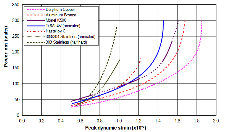
- 图 9。15 kHz 下声学材料的超声功率损耗
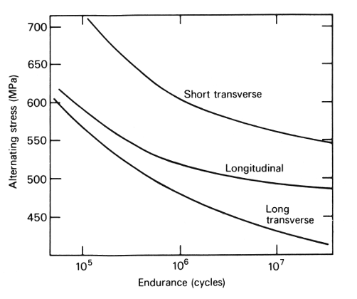
- 图 10。57 mm 厚 Ti-6Al-4V 锻造退火棒材试验方向对疲劳的影响(旋转悬臂试验)
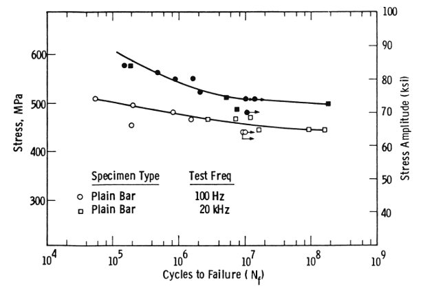
- 图 11。加工工艺对 Ti-6Al-4V 疲劳的影响
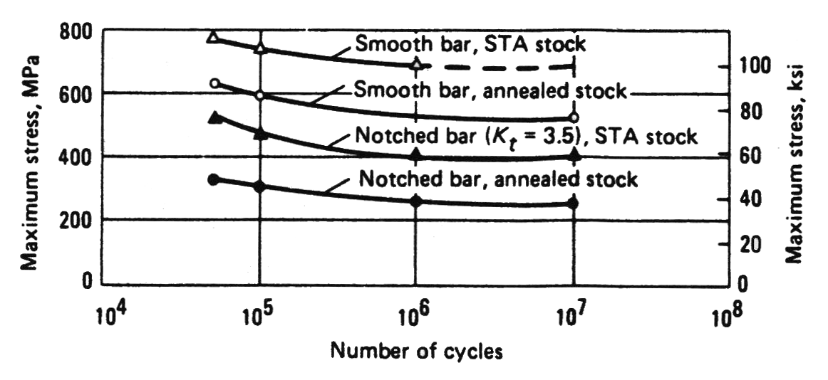
- 图 12。Ti-6Al-4V 退火态与 STA 态的 S-N 疲劳曲线(旋转弯曲试验)
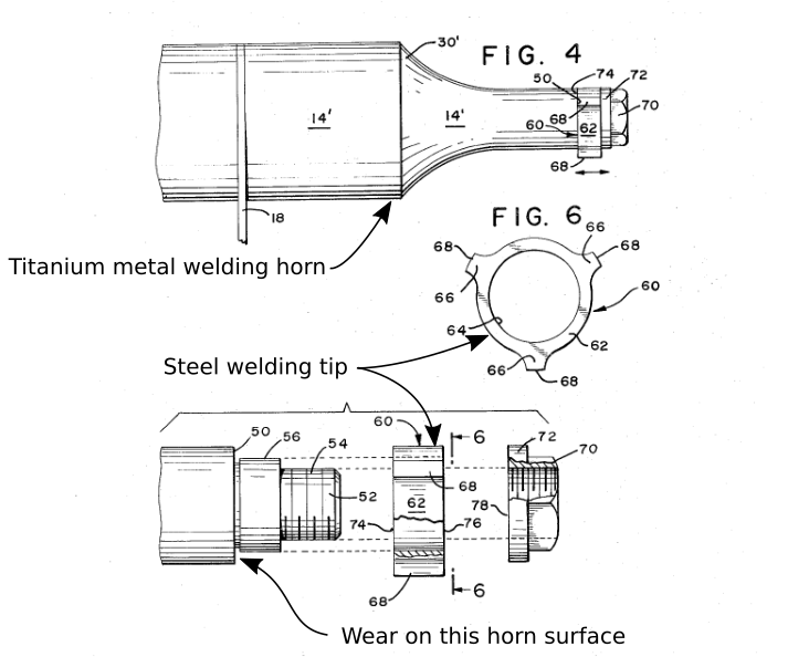
- 图 13。Branson Ultrasonics 金属焊接变幅杆
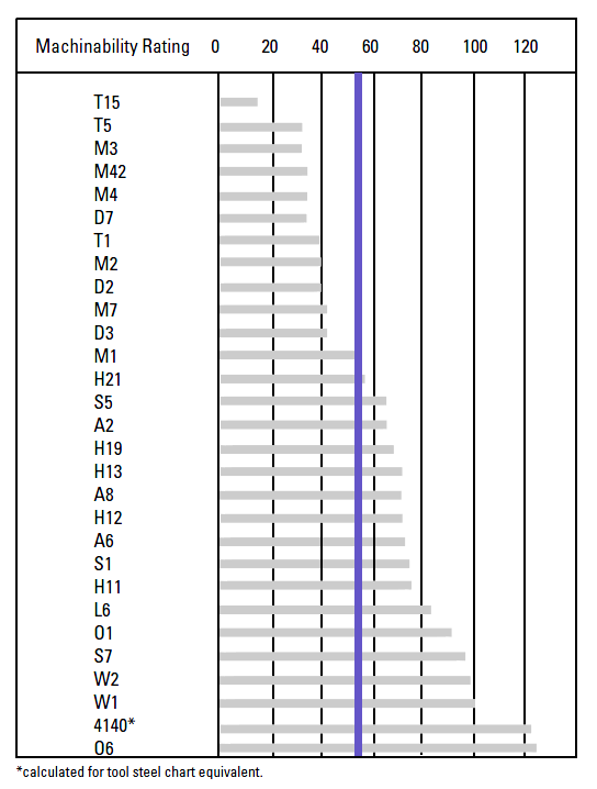
- 图 14。Ti-6Al-4V 相对于各种工具钢的可加工性
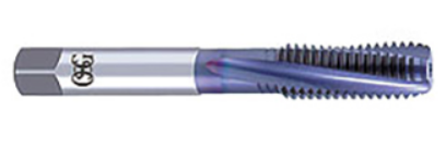
- 图 15。螺旋槽丝锥(来自 OSG USA)
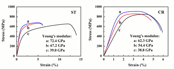
- 图 C1。固溶处理(ST)与冷轧(CR)试样的应力–应变曲线 — (a) Ti‑5Nb‑9Zr,(b) Ti‑10Nb‑9Zr,(c) Ti‑15Nb‑9Zr
用途
钛合金因其良好的综合声学性能而被采用。
- 高应力谐振器的长寿命。
- 适用于外科手术器械或植入物的生物相容性。
- 中等的抗冲击、耐磨损和抗空化冲蚀能力。
- 耐化学腐蚀性。
然而,钛相对昂贵,因此在合适的场合应选用其他材料。
应用包括医疗(外科)、塑料焊接与金属焊接、液体处理,以及食品包装和切割。
交叉引用
各种牌号钛的规范对照表可以在这里找到。该对照表包含美国、英国、法国和德国的牌号命名。
命名规则
钛合金按其主要合金元素命名(名义重量百分比);但也可能含有其他微量元素。例如,Ti-6Al-4V 表示一种名义上含 6% 铝和 4% 钒的合金。
重要提示— 仅凭化学成分不足以判定钛合金的性能。(这就好比只凭酿酒所用的葡萄品种来评价一瓶酒。)相反,必须规定整个热机械加工生产过程(它决定了显微组织)。
性能
正交各向异性方面的考虑
钛是正交各向异性的,这意味着材料性能取决于测试方向相对于晶粒方向的取向。晶粒方向通常标记为纵向 L(即平行于晶粒方向)、横向 T(也称长横向 LT)和短横向 ST。参见下图(引自 Bowen[1],第 1273 页)。
|
|
|
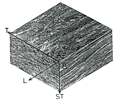
Bowen(第 1272 页)列出了该材料的以下性能。请注意性能对测试方向的显著依赖性。
|
||||||||||||||||||||||||
|
表格注释:
- 材料为 Ti-6Al-4V,锻造并退火,宽 235 mm x 厚 57 mm。
- E = 杨氏模量。
- 细杆波速 \( c_{tw} \) 按 \( \sqrt{E/\rho} \) 计算,其中假定密度 \( \rho \) 为 4430 kg/m3。这些 \( c_{tw} \) 数值未包含在 Bowen 的原始表格中。
- 疲劳强度为 107 次循环下的近似值。
对于钛,杨氏模量和波速取决于以下因素:
- 振动方向相对于晶粒方向的取向(见上表)。
- 原材料在棒材长度方向上的位置。
- 生产试样所用的炉次。同一炉次的不同试样之间也可能存在差异(见下文)。
- 毛坯类型(圆棒、棒材、薄板或板材)。
- 对于圆棒材料,还有毛坯直径(见下文)。
因此,由于钛的波速或弹性模量可能无法精确获知,钛谐振器的调谐长度将不能完全复现,即使使用计算机仿真也可能无法精确预测。
交叉轧制
钛的方向性可以通过交叉轧制来降低。在该工艺中,板材在减薄厚度的过程中沿相互垂直的方向依次轧制。Arthington[1](第 6 页)报告说,TIMET 在为 Rolls Royce plc 制造的高可靠性航空发动机压气机叶片上采用了这一工艺。
损耗(Q)
Ti-6Al-4V 的数据请参见此处。
随晶粒方向的变化
有限的实验数据表明,损耗取决于振动方向相对于晶粒方向的取向。
疲劳特性
钛合金具有持久极限(应力),低于该极限材料将具有无限寿命。然而,该持久极限的确切数值较难确定。关于 Ti-6Al-4V,请参见下文的讨论。
磨损
磨粒磨损
钛的耐磨粒磨损性能明显优于铝,但不如淬硬钢。有几种方法可以提高其耐磨性。
镶嵌块
可以将碳化钛(TiC)镶嵌块钎焊到平端面钛变幅杆上。
- 对于高振幅条形变幅杆,经验表明镶嵌块厚度应小于约 1.8 mm,以限制惯性力,否则可能导致镶嵌块从变幅杆上脱落。此外,由于碳化物相对较脆,每块镶嵌块的宽度应限制在约 25 mm,以免碳化物因变幅杆端面上振幅不均匀而开裂。当然,这些建议尺寸可以根据变幅杆的振幅和均匀性进行调整。
- 钎焊时必须特别小心,以确保变幅杆与碳化物之间形成牢固的连接。
- 碳化钨的密度(15600 kg/m³)约为碳化钛(4930 kg/m³)的三倍。使用碳化钨会使变幅杆与碳化物连接处承受的应力增至 3 倍。因此,通常优先选用碳化钛而非碳化钨。
涂层
与镶嵌块不同,涂层可以施加在非平面上,而且涂覆工艺可能更简便。然而,由于这些涂层的厚度一般较为有限,加之钛基体相对较软,它们不一定能提供良好的抗冲击能力。此外,许多涂层不应施加在高应力区域,因为这可能降低变幅杆的疲劳寿命。因此,可能需要对变幅杆进行遮蔽保护。
D‑Gun
D‑Gun 是 Union Carbide 开发的专有工艺,现由 Praxair[1] 提供。有多种涂层可供选择,在超声应用中的典型厚度可达约 1 mm。
有一家汽车客户对玻纤填充树脂进行超声铆接,采用 0.025 mm–0.050 mm 的 D‑Gun 涂层后,磨损寿命达到正常水平的八倍。磨损寿命终结后,将残余的 D‑gun 涂层剥离并对变幅杆重新涂覆。
LW‑1N30(主要为碳化钨,Rc 70)已成功应用于铝制 40 kHz 织机分切变幅杆(在织机上织布的同时对布边进行分切并同步封边)。
扩散表面硬化
"扩散硬化的做法是:根据所采用的扩散工艺类型,用待扩散元素的固相、液相或气相将金属零件完全包围。零件周围扩散元素的浓度必须高于零件内部该元素的浓度,否则扩散不会发生。然后将金属和周围元素加热到足以发生扩散的温度。"(https://en.wikipedia.org/wiki/Diffusion_hardening)
扩散进去的间隙原子浓度主要集中在钛基体表面附近,并随深度迅速下降,因此硬度也呈类似的分布规律。有效硬化深度可达约 50 微米(参见 Güleryüz[1])。
Ti-6Al-4V 的硬度通常取 35 HRC(洛氏 C),约相当于维氏硬度 350。Güleryüz[1] 表明,用氧、氮、硼进行扩散硬化分别可获得 1200、2000 和 2700 的表面硬度(维氏)。具体结果取决于工艺条件,包括温度和保温时间。
应评估扩散硬化对疲劳的影响。对于生物医学应用,还应考察发生剥落的可能性。摩擦可能会有所降低。
空化冲蚀
Ti-6Al-4V
当需要使用钛合金时,最常用的是 Ti-6Al-4V(6% 铝、4% 钒),部分原因是它来源广泛。(截至 2000 年,Donachie[1] (第 15 页)报告其市场份额为 50%。)由于该合金在非超声领域(尤其是航空航天)应用广泛,已积累了庞大的知识库。Ti-6Al-4V 已在美国及其他国家获准用于超声外科器械。
说明—
- 本节的许多讨论是针对退火态 Ti-6Al-4V 的。不过,某些信息(如密度)适用于所有状态的 Ti-6Al-4V。
- Ti-6Al-4V 只规定了化学成分。某些性能(因而也包括使用性能)可能因晶粒方向、热处理、加工工艺等因素而有相当大的差异。
化学成分
下表列出了 Ti-6Al-4V 允许的元素及其含量(TIMET[1],第 1 页)—
|
|||||||||||||||||||||||||||||||||
|
密度
Ti-6Al-4V 的常用密度为 4430 kg/m³。
Ti-6Al-4V — 退火态
弹性模量与波速的变化
圆柱形棒料
对于退火态圆柱形棒料,Culp[0] 及其同事的多项测试表明,杨氏模量取决于材料的毛坯直径(即加工出谐振器的原材料直径)。
|
|
|
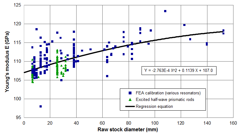
图 2 中的每个数据点均由以下两种方法之一获得。
- FEA 标定。测量每个谐振器的频率,并将该实测频率与在假定杨氏模量下得到的 FEA 频率进行比较;然后调整假定的杨氏模量,直到 FEA 频率与实测频率一致。(测量频率时,谐振器被刚性连接到一个标称频率与谐振器相同的换能器上,因此换能器可能对实测频率产生一定影响。)
- 受激半波棱柱杆。将一根半波棱柱杆(长度 \( \Gamma \))轻轻置于换能器上方,用非接触式仪器测量杆自由端的振幅。调节换能器的驱动频率 \( f \),直到杆的轴向振幅达到最大(即对应杆的基频轴向谐振)。然后按下式计算细杆波速 \( c_{tw} \)—
\begin{align} \label{eq:15101a} c_{tw} = (2 \Gamma) f \end{align}
再由下式计算杨氏模量—\begin{align} \label{eq:15102a} E = c_{tw}^2 \, \rho \end{align}
两种方法所用的材料均来自众多熔炼炉次和供应商,未能从中找出任何规律。
这些结果的可信度很高。因此,数据离散很可能源于钛材料本身的实际差异,而非测量误差。这是钛材料的一个已知问题。(参见下文的进一步讨论。)
利用图 2 中杨氏模量的回归方程,可以计算细杆波速(\( \sqrt{E/\rho} \))(图 3)。
|
|
|
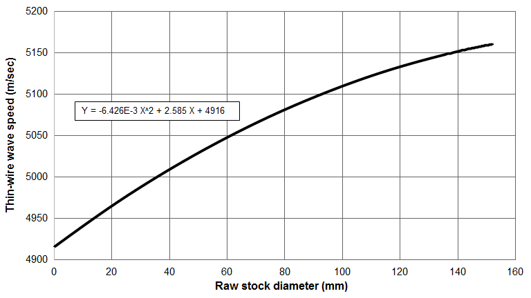
数据离散性
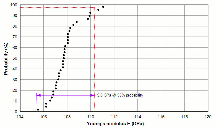
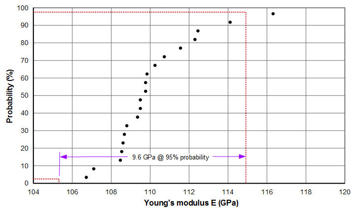
在图 2 的数据中,有三种直径拥有数量可观的样本:7.9 mm、12.7 mm 和 38.1 mm。以下三幅图显示了这些直径下数据的离散程度及相应的概率。例如,对于 38.1 mm 直径(图 4c),95% 的杨氏模量落在 9.6 GPa 的区间内,均值为 111.8 GPa。(38.1 mm 直径的原始数据见附录 A。)
|
|
|
|
|
|
|
|
|
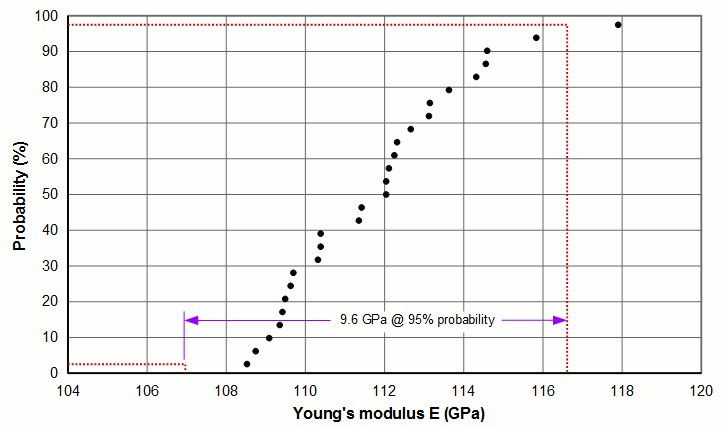
下表汇总了上述图形信息。请注意,95% 概率是在假定数据服从正态分布的条件下计算的。这一假定并不完全正确,同一材料直径下均值与中位数存在差异这一点就部分说明了问题。
遗憾的是,上图所示的数据离散对钛而言并不罕见。图 5 显示了八个炉次 Ti-6Al-4V 薄板在纵向和横向两个材料方向上的类似离散情况(TIMET 数据[1],第 14 页)。在室温下,两个材料方向的数据离散均约为 ±2.8 GPa。(从正交各向异性的角度看,室温下横向的平均杨氏模量(约 118 GPa)比纵向(约 107 GPa)高约 5%。)
|
|
|
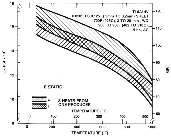
上图中,WQ = 水淬;AC = 空冷。
Culp[0] 对一种未公开牌号钛合金(锻造态)的数据表明,杨氏模量甚至可沿单根棒材的长度方向变化。在这些测试中,激励端和拾振端均采用静电方式,因此没有附加换能器干扰测试结果。
|
||||||||||||||||||||||||||||||||||||
|
重复测试表明数据具有很好的复现性。因此,杨氏模量沿棒长的变化必然源于材料性能的实际差异,而非测试误差。
有趣的是,该材料纵向的杨氏模量高于长横向。然而,这与该材料的其他已知数据相矛盾。
板料
由于钛是正交各向异性的,三个材料方向(纵向、横向、短横向)上的弹性模量可能各不相同。这类信息无疑存在(掌握在飞机制造商手中),但似乎并未公开。
Culp[0] 汇总了一批变幅杆的数据,这些变幅杆的纵向材料方向与主振动方向(螺柱轴线)平行。测试过程和数据见附录 B。剔除 132.4 GPa 这一个离群值后,平均模量为 119.6 GPa。除这一个离群值外,数据离散程度合理,且似乎与变幅杆厚度无关。
泊松比
文献报告的泊松比数值范围很宽。这些数值受到与波速和弹性模量(见上文)相同因素的影响。
- "很难为钛合金给出一个可靠的泊松比数值,因为各向异性会导致弹性模量和剪切模量均有微小差异,二者联合用于计算泊松比时,可能使退火态 ASTM Grade 5 (Ti-6%Al-4%V) 薄板的泊松比在 0.287 至 0.391 之间变化。不过,工业纯钛普遍接受的数值为 0.36,ASTM Grade 5 为 0.31。"(AZO Materials)
- "泊松比取决于材料织构和测量方向。TIMET 用双元件应变花进行了十次观测,得到均值 0.342,观测范围为 0.287 至 0.391。"(TIMET[1],第 15 页)
- Barile[1] 对 Ti-6Al-4V 取 0.32,并称其为"……一种各向同性且均质的钛合金"(第 161 页)。该数值是否由实验确定尚不清楚。
- Hampton[1](第 33 页)在分析一个带 Ø45 mm Ti-6Al-4V 前驱动块的 30 kHz 换能器时取 0.334。该数值的来源不详。
- 对于 1 mm 厚的 Ti-6Al-4V 薄板材料,Lecompte[1] 报告的实验值为 0.385,由 FEA 反算的值为 0.36 ± 0.02。
- Wuchinich[5] 测量了 Ø63.6 mm 和 Ø82.5 mm 两个 Ti-6Al-4V 圆柱的弯曲和扭转频率,然后标定 FEA 模型的材料属性,使 FEA 频率与实测频率一致。两个圆柱标定出的泊松比均为 0.288。(两个圆柱标定出的杨氏模量分别为 114 GPa 和 112 GPa,均落在图 2 的数据离散范围内。)
- McCulloch[1](第 524 页)在分析一把 35 kHz 切割刀片时取 0.31。该数值的来源不详。(钛的牌号未注明,但假定为 Ti-6Al-4V。)
- Derks[1](第 11 页)对一种"钛合金"给出 0.305。该数值的来源不详。(合金牌号未注明,但假定为 Ti-6Al-4V。)
- Culp[0] 发现,泊松比取 0.32 至 0.34 之间时 FEA 结果较为合理。
- matweb.com 给出的数值为 0.342。
损耗(Q)
如下表所示,Ti-6Al-4V 在退火态下损耗最低(Q 最高)。(据信这些测试所用的毛坯均为圆柱形棒料。)
|
||||||||||||||||||||||||||||||
|
注释—
- Wuchinich[2] 的材料加热到 940 °C(1725 °F)保温一小时后水淬,洛氏 C 硬度 HRC 为 65(第 4 页)。
- 下文图 6中 Mason[1] 的材料在真空中于 760 °C(1400 °F)退火一小时(第 1927 页)。
- 下文图 7中 Mason[1] 的材料为"未退火",这似乎表明它处于供货原始状态,但这一点并不明确。
Mason[1] 在 17.6 kHz 下对退火态 Ti-6Al-4V 试样进行了不同应变水平的测量(图 6;见上文表 5 和注释 2)。(注:为清晰起见,图 6 中删除了 Mason 原图中的一些无关曲线。)Mason 发现,内耗(Q 的倒数)在应变约 0.003 以内保持恒定,为 0.00005(Q = 20000)(第 1925 页),超过该应变后内耗迅速增大(即损耗增大、Q 下降)。该极限应变对应约 320 MPa [46 kpsi] 的应力。Mason 还发现,内耗的增大不一定能通过后续退火恢复(第 1926 页)。(Wood[1] 在 20 kHz 下测试退火钛(牌号未知)时发现了类似的现象。)
|
|
|
|
在低振幅测试中,Mason 发现内耗在高达 104 kHz 的频率范围内与频率无关,且在高温下"仅略有"下降(图 7;见上文表 5 和注释 3)。
|
|
|
离散性
在上述 Mason 的工作中,受测试样数量未知,因此离散性也无从得知。不过,Mason 的图 7(第 1931 页)显示,两个充分退火试样的内耗相差近 2:1。
Wuchinich[3] 报告两个退火试样的 Q 约为 5000,仅为 Mason[1] 报告值的 1/4。
与其他材料的比较
Aeroprojects 曾对多种金属进行谐振测试以测定其声学损耗(约 1969 年)。测试方法是让水流过一个高应力 15 kHz 变幅杆的中心孔,测量水的温升(图 8)。
|
|
|
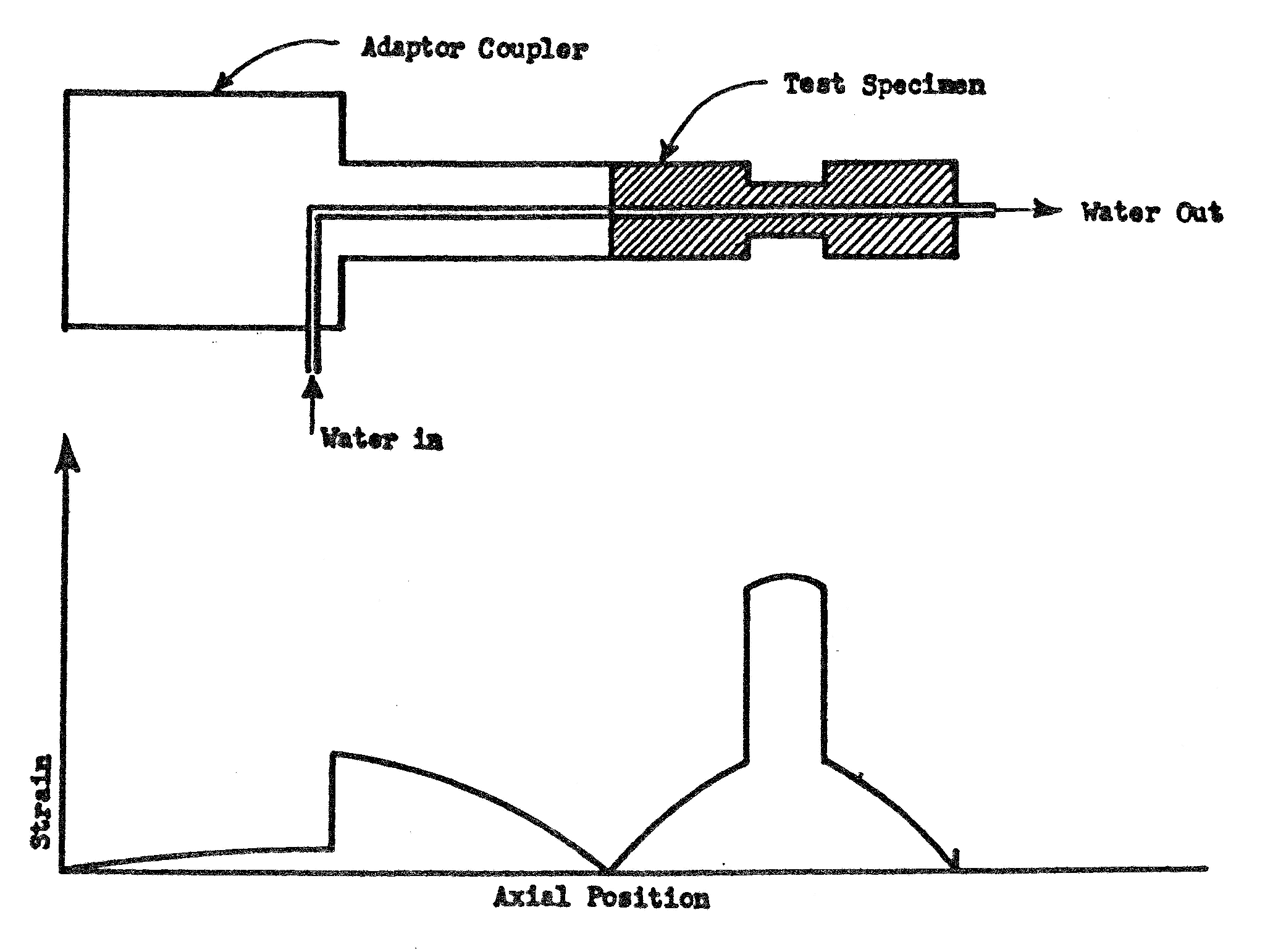
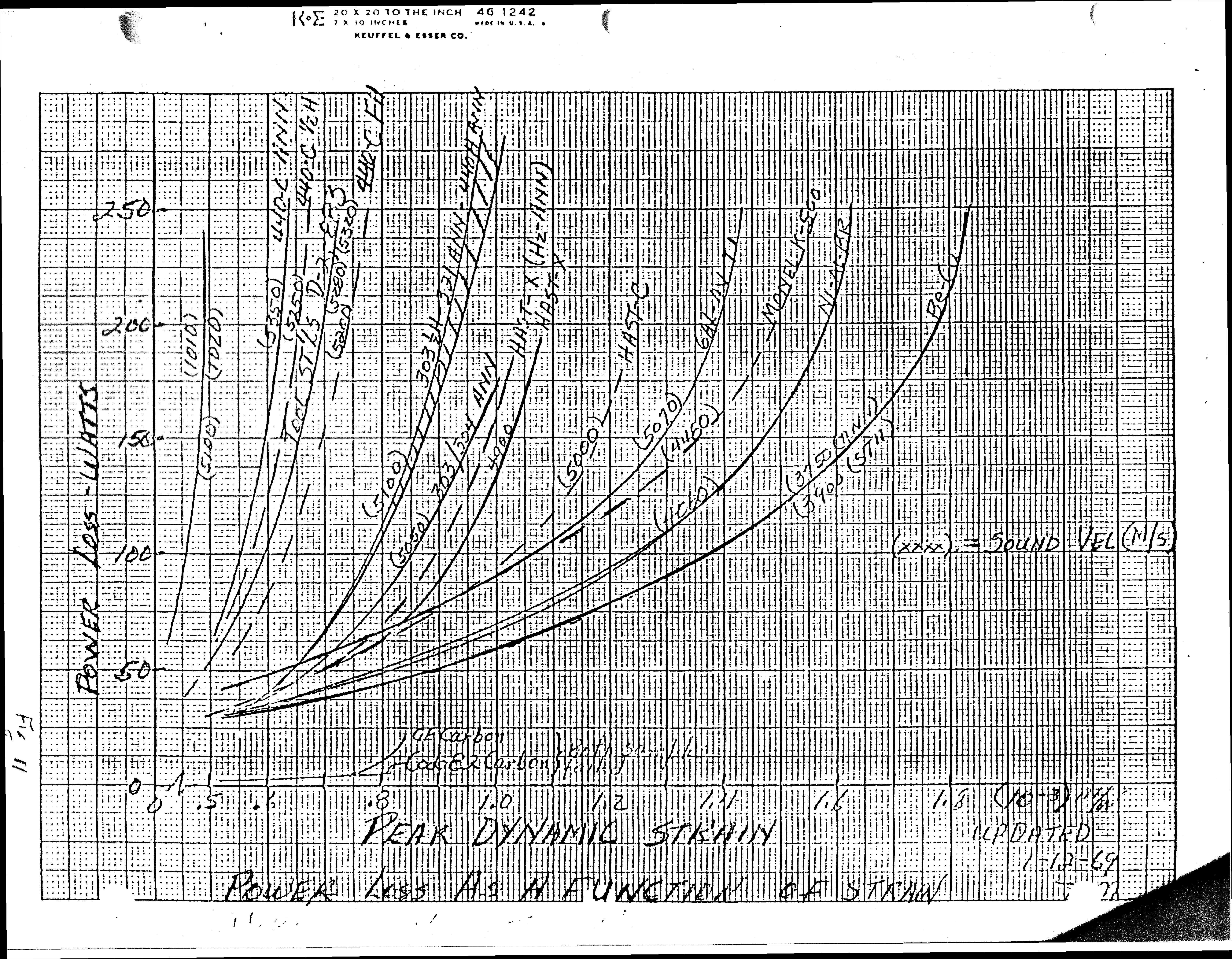
测试结果(由 Maropis[0] 提供给 Culp[0])如图 9 所示。请注意,这些损耗数值仅对特定频率和试样形状有效,但各材料之间的比较仍然成立。
Aeroprojects 的数据表明,Ti-6Al-4V 的损耗随应变增大而持续增加,且在较高应变下损耗加速上升。数据还显示 Ti-6Al-4V 优于受测的各种钢。虽然 Ti-6Al-4V 的损耗高于铍铜、铝青铜和蒙乃尔 K500,但它可能具有其他优势(如价格更低、疲劳强度更高、可加工性更好等)。
注释—
- Aeroprojects 原始手绘图(含损耗更高的其他钢种)请见此处。
- 图 9 中 Aeroprojects 的结果是损耗,而图 6 中 Mason 的结果是 Q 值,因此两组结果无法直接比较。
|
|
|
疲劳
参见疲劳的一般性讨论。此外,以下内容专门针对钛。
在将实际工况下的疲劳与实验室 S‑NL 数据进行比较、以及解读 S‑NL 曲线图时,应考虑以下因素。
晶粒方向
疲劳可能受晶粒方向相对于主应力方向的影响。例如,参见下文 Boyer[1](第 431 页)的图。(原始出处:Polmear, I. J., Light Alloys, American Society for Metals, Metals Park, OH, 1981, p. 193)请注意,与上文 Bowen 的数据不同,此处纵向的寿命明显长于长横向。
交叉轧制对疲劳的影响尚不清楚。不过,鉴于该工艺所服务的航空发动机压气机叶片对可靠性的苛刻要求,可以推定其疲劳性能应相当出色。
|
|
|
蚀刻
钛的晶粒方向可用 Kroll 试剂(1% HF(氢氟酸)、12% HNO3(硝酸)、余量为水)检验(机加工前或加工后均可),该试剂有市售产品。
频率
在没有特殊干扰因素的情况下,超声疲劳试验结果通常与常规低频 S‑N 疲劳试验相当吻合(示例见图 11),但这一问题尚未完全定论。参见 Wells[1]。另见 Neppiras[1B](第 707 页),他指出:"测量已经证实,疲劳极限是工作频率的函数【比较超声试验结果与低频试验结果】。"(但请注意,这一说法并非专门针对钛。)
成形工艺
材料可以通过锻造、挤压、轧制、交叉轧制等方式成形,每种方式都可能产生不同的疲劳性能。
热处理
钛的热处理会影响持久极限。例如,matweb.com 给出的通用退火态无缺口 Ti–6Al–4V 在 107 次循环下的数值为 510 MPa,而 STA(固溶处理并时效)态为 700 MPa。但有关重要的缺口结果,请参见附录 E。(重要提示:试验条件未注明,因此这些持久极限数值只能用于相互比较。)
缺口敏感性
有些材料在无缺口状态下疲劳性能良好,但在缺口状态下性能下降相对明显。Ti–6Al–4V STA 的缺口敏感性见附录 E。
残余应力
残余拉应力可能降低疲劳寿命。另一方面,Donachie[1](第 177 页)指出:"关于钛合金还有一点值得注意:文献中报告的疲劳数据往往来自因车削、铣削等加工而在表层形成有利残余应力的材料。完全消除应力的表面或化学铣削表面的疲劳强度很可能低于文献报告的合金水平,因为后者被有利的——即压应力——残余应力抬高了。"
请注意,某些机加工操作(如过于剧烈的电火花加工 EDM(另处讨论)、剧烈的磨削)可能引入较高的残余拉应力。
加工工艺
疲劳可能受材料加工方式及其形成的显微组织的影响。图 11(Willertz[1],第 341 页)以细晶 α‑β 材料在纯水中测试为例显示了这种影响:片层状组织的性能明显优于等轴组织。试样为圆柱形,因此材料形态不是薄板;但其他信息不详。(请注意,此例中常规频率与超声频率的测试结果总体上相当一致。)
|
|
|
推荐的最大应力和应变
综合考虑损耗和疲劳,最大应力一般应限制在 320 MPa [46 kpsi;约 0.0029 应变]—350 MPa [50 kpsi;约 0.0032 应变]。
- 损耗。如前所述,应变超过 0.003 后损耗会迅速增大,这对应约 320 MPa 的应力(但具体数值取决于杨氏模量,而杨氏模量可能有所波动)。对于细长的谐振器,附加冷却(如外科器械的水冷)可能允许更高的应力。然而,对于相对粗厚的谐振器(如条形变幅杆),由于钛的导热性差,附加的表面冷却可能无法有效带走热量,此时可能需要降低应力。
- 疲劳。考虑到疲劳涉及的诸多变量,对于主振动方向平行于纵向晶粒方向的退火态 Ti-6Al-4V,文献和经验表明(作为粗略的经验法则):在正常条件下(表面光洁度合理、无残余应力、无腐蚀介质等),最大峰值交变应力不应超过 350 MPa [50 kpsi;约 0.0032 应变](假定要求基本无限寿命)。
(Wuchinich[4](第 7 页)断言:"实验已经确定,安全的振动应力值为屈服应力(金属开始发生不可逆变形的应力)的三分之一。"据此,最大安全应力约为 300 MPa [43 kpsi;约 0.0027 应变]。
Mathieson[1](第 58 页)给出的限值为 200 MPa [29 kpsi;约 0.0018 应变]。
Bromfield[4](第 16 页)给出的限值为 390 MPa [57 kpsi;约 0.0035 应变]。
上述数值均以加工得当为前提— 即良好的表面光洁度和低残余应力。
特殊情况可能允许稍高的应力,也可能要求更低的应力。对于失效后果严重的应用(如外科探头),宜采用更低的应力限值。
Ti-6Al-4V — 其他状态
除退火态外,Ti-6Al-4V 还有 STA(固溶处理并时效)态和 ELI(超低间隙元素)态可供选用。
Ti-6Al-4V STA(固溶处理并时效)
固溶处理并时效是提高 Ti-6Al-4V 强度的常用方法。(详见 TIMET[1],第 10 页。)下表(来自 matweb.com)将 Ti-6Al-4V STA 与退火态 Ti-6Al-4V 进行了对比(为完整起见,也列入了 ELI 材料)。在多数方面,Ti-6Al-4V STA 似乎更优,例如其无缺口(Kt = 1.0)疲劳强度高出 37%。然而,许多超声谐振器因开槽、开筋等圆角而存在明显的"缺口"(应力集中)。matweb 数据显示,当应力集中系数 Kt = 3.3 时,Ti-6Al-4V STA 的疲劳强度实际上比退火态低 33%。(Osgood[1](第 440‑442 页)指出,钛对缺口非常敏感,而热处理会加剧这种缺口效应。)
|
||||||||||||||||||||||||||||
|
然而,与上述结论相反,下文 Boyer[1](第 430 页)的图表明,STA 在无缺口和缺口两种状态下的疲劳性能都更优。(原始出处:Metals Handbook, 9th Edition, Volume 3, Properties and Selection: Stainless Steels, Tool Materials and Special‑Purpose Metals, American Society for Metals, Metals Park, OH, 1980, p. 389)因此,STA 与退火态相比疲劳性能孰优尚不明确。不过,如前所述,STA 材料的损耗更高(Q 更低),这可能限制其在高应力下工作的能力。
|
|
|
Ti-6Al-4V ELI(超低间隙元素)
Ti-6Al-4V ELI 是 Ti-6Al-4V 的高纯度("超低间隙元素")版本,对铁以及碳、尤其是氧等间隙元素规定了更低的含量上限。这带来了更优异的韧性,在低温下尤其明显。
有迹象表明,这种材料可能更适合超声应用,无论是因其杨氏模量更稳定,还是疲劳强度更高。Osgood[1](图 10.49,第 422 页)列出的 Ti-6Al-4V ELI 无缺口疲劳强度在 107 次循环下为 635 MPa [92 kpsi],而 Ti-6Al-4V 为 515 MPa [75 kpsi],提高了 23%。(Osgood 未注明材料状态。)另一方面,matweb.com 给出的 Ti-6Al-4V ELI 数值为 300 MPa [44 kpsi],而相同条件下 Ti-6Al-4V 退火材料为 510 MPa [74 kpsi](降低了 41%)。
Ti-7Al-4Mo
尽管大多数谐振器制造商使用 Ti-6Al-4V,Branson Ultrasonics 使用的是 Ti-7Al-4Mo(7% 铝、4% 钼),通常由 TIMET 供货。Branson 于 20 世纪 70 年代初从 Ti-6Al-4V 改用 Ti-7Al-4Mo。
- 在 Branson 超声金属焊接机的研制过程中,钢焊接环焊接凸耳处的超声焊接应力最终会导致相邻的变幅杆配合面劣化(图 13)。Ti-7Al-4Mo 似乎能带来更长的寿命。
- Ti-7Al-4Mo 似乎能减小调谐长度的波动(即杨氏模量更稳定)。
|
|
|
文献表明,该材料的疲劳强度可能高于 Ti-6Al-4V。一个来源(由 Culp[0] 报告)发现,带切削螺纹的钛端头用 Ti-7Al-4Mo 制造时比用 Ti-6Al-4V 更不易发生螺纹疲劳失效。 (这些材料是退火态还是 STA 态尚不清楚。)
|
||||||||||||||||
|
表 8 列出了 Ti-7Al-4Mo 相对于 Ti-6Al-4V 所宣称的优势(Branson 的 Technolog TL-18)。(注— Technolog 未注明 Ti-7Al-4Mo 的状态。不过,对照表 7 中的极限强度和屈服强度,Branson 的材料似乎是退火态而非 STA 态。)
|
||||||||||||||
|
表格讨论注释—
- 对大多数谐振器而言,只要材料强度足以防止螺柱孔螺纹滑扣,材料强度就无关紧要。不过,对于冲击类应用(例如配可更换端头的金属焊接变幅杆),强度更高的材料会有好处。
- 在任何合理的工作温度下,超声谐振器所受的拉伸或压缩都不足以引起蠕变。因此蠕变无关紧要。
- 有此可能,但未提供数据。
- 除非这是指 Ti-7Al-4Mo 更接近各向同性,否则含义不明。即便如此,其性能上的好处也不明确。不过,(按各向同性材料属性建模的)FEA 结果会更贴近实际谐振器。
- 谐振器的最大许用应力由材料的疲劳强度决定。由于疲劳一般发生在缺口处(如槽端),缺口疲劳强度才是限制因素。
对于无缺口钛,疲劳强度随极限抗拉强度近似线性提高(Osgood[1],第 441 页)。例如,表 9 对比了 Ti-6Al-4V STA 材料(极限强度 1170 GPa)与退火态 Ti-6Al-4V(极限强度 950 GPa)。无缺口时,STA 材料的疲劳强度高出 38%;然而,当两种材料都加上应力集中系数 3.3 的缺口后,STA 材料的疲劳强度反而低 33%。
再看 Ti-7Al-4Mo。其极限抗拉强度比 Ti-6Al-4V 高 15%(按 Branson 的数据为 1040 MPa 对 900 MPa),其无缺口疲劳强度很可能更高。然而,并不能保证 Ti-7Al-4Mo 具有更好的缺口疲劳强度——事实上可能更差。 - 几乎所有谐振器都是从端面进行调谐的,调谐时只有材料的质量密度起作用。鉴于从端面去除的材料长度很小(20 kHz 时通常小于 6 mm),在这一距离内密度出现显著变化(从而导致调谐速率变化)的可能性微乎其微。
|
|||||||||||||||
|
表格注释—
- STA = 固溶处理(即淬火)并时效
- 疲劳强度数值均为 107 次循环下的数值。
密度
Ti-7Al-4Mo 的常用密度为 4484 kg/m³。请注意,这比 Ti-6Al-4V(4430 kg/m³)高 1.3%。
弹性模量与波速的变化
加工制造
常规机械加工
"在以 AISI B1112 钢为基准的评级体系中,Ti-6Al-4V 的可加工性为 B1112 的 22%。一般推荐采用低切削速度、大进给量和充足的切削液。此外,由于钛有很强的咬合和涂抹倾向,刀具与工件在接触运动过程中绝不可停止进给。应使用无氯切削液,以消除氯化物污染的可能。需要注意的是,钛屑高度易燃,必须采取适当的安全防护措施。"(Carpenter[1],第 6 页)
图 14 显示了 Ti-6Al-4V 与各种钢材的可加工性对比。该数据的基准为 W1 钢(一种水淬硬化钢) ,取为 100(Bryson[1],第 141 页)。在 AISI B1112 标尺上,W1 的可加工性为 40%(Bryson[1],第 141 页)。(注— 图中竖直蓝线为后加的,它表示 Ti-6Al-4V 的可加工性,在 AISI B1112 标尺上为 22%,即相当于 W1 的 55%。)
|
|
|
注释—
- 推荐使用硬质合金刀具。
攻丝
钛攻丝可能比较困难,因为它导热性差。积聚的热量可能导致切削刃崩缺并缩短丝锥寿命。此外,钛容易咬住丝锥,造成螺纹的咬合和撕裂;这还可能导致小直径丝锥折断。
加工硬化——
有钛专用的特殊丝锥可供选用(图 15)。
|
|
|
攻丝前底孔的尺寸取决于钻头的精度和状况、制孔所用设备的类型(例如数控还是手动操作)等因素。因此,应规定钻孔直径的极限范围,而不是规定某个特定的攻丝底孔钻头尺寸。
深孔钻削
钛医疗探头常需加工深的小直径孔作为流体通道。这类孔用枪钻比用普通麻花钻更容易、更精确地加工。枪钻只有一条纵向排屑槽,因此刚性比麻花钻好,而且带有一个供冷却润滑液通过的中心孔。
电火花加工(EDM)
电火花加工(EDM)曾被尝试用于在块形变幅杆上加工槽。但该工艺相对较慢,且会降低疲劳寿命。详情……此外,许多工厂没有自己的 EDM 设备,依赖外协供应商可能延长生产周期并影响质量控制。
建议
- 为保证材料性能的一致性,应始终从同一供应商采购材料,最好还来自同一制造商。
- 务必在谐振器图纸上标明晶粒方向。
- 虽然有些矩形变幅杆尺寸太大、无法用棒料加工,但大多数矩形变幅杆可以用板料加工。因此,为获得最高的一致性,矩形变幅杆应尽可能采用板料。
- 在材料尺寸允许的情况下,圆柱形变幅杆应采用圆柱形棒料而非板料加工。这是因为,尽管材料性能可能沿径向变化,但沿圆周方向应几乎没有变化,从而可将任意给定半径处的振幅变化降至最低。(如果变幅杆用板料加工、螺柱轴线沿厚度(短横向)方向,那么由于板材在纵向和长横向两个材料方向上的性能差异——这两个方向都垂直于螺柱轴线——给定半径处的振幅就可能发生变化。)
- 按优先顺序,晶粒方向(相对于谐振器主应力方向)应指定为:1) 短横向,2) 纵向,3) 长横向。不过,短横向可能没有足够尺寸的料可供选用。
- 对于 Ti-6Al-4V—
- 应选用退火态材料,因其疲劳性能更好、损耗比 STA 态更低。
- 杨氏模量
- 对于圆柱形棒料,杨氏模量可取自图 2。
- 对于晶粒方向平行于主振动方向的板料,119.6 GPa 是杨氏模量合理的初步估计值。
- 最大应力。
附录 A — Ø38.1 mm Ti-6Al-4V 圆棒的杨氏模量
|
||||||||||||||||||||||||||||||||||||||||||||||||||||||||||||||||||||||||||||||||||||||||||
|
注释:
- 数据来自 Culp[0]。
附录 B — Ti-6Al-4V 板材的杨氏模量
纵向晶粒方向
一批变幅杆加工时使晶粒方向与主振动方向平行。对每根变幅杆进行 FEA 分析,调整杨氏模量直到 FEA 频率与实际变幅杆的实测频率一致。这样确定的杨氏模量相当于把材料当作各向同性处理,尽管它很可能是正交各向异性的。
|
||||||||||||||||||||||||||||||||||||||||||||||||||||||||||||||||
|
注释:
- 数据来自 Culp[0]。
- 所有变幅杆均为条形变幅杆。
- 变幅杆尺寸按"端面宽度" x "端面厚度" x "背面厚度"的顺序列出。
- 所有尺寸均圆整到最接近的 mm。
- TIMET[2] 是一家钛材制造商。President Titanium[1] 是一家经销多种来源钛材的供应商。
- 35 kHz 的 83 mm x 5 mm x 23 mm 变幅杆模量为 132.4 GPa,疑似离群值。若剔除该数据,平均模量变为 119.6 GPa(–0.5%)。
- 在这类测试中,附加的换能器可能对频率、进而对确定的模量产生一定影响。
附录 C — 低杨氏模量钛合金
以下钛合金的杨氏模量明显低于正常水平。这会降低波速,从而在规定频率下得到更短的调谐长度。
Niinomi[1A](第 2 页)指出:"在提高疲劳强度的同时降低杨氏模量是比较困难的,因为从原子间结合力的角度看,二者的变化方向相反。"这类合金中许多都含铌(Nb)。
这些钛合金可用于骨植入物,因为它们的低模量更接近骨骼的模量。
以下清单并不全面。
Ti‑29Nb‑13Ta‑4.6Zr (TNTZ)
Niinomi[1A] 报告的模量为 60 GPa(严重冷加工态为 55 GPa)。在某些条件下,该材料的疲劳强度可与 Ti-6Al-4V ELI 相当(Niinomi[1A],图 10,第 3 页)。该材料可用于生物医学应用。(另见 Niinomi[1B]。)
Ti‑(5, 10, 15)Nb‑9Zr
Liu[1] 研究了 Nb(铌)含量分别为 5%、10% 和 15% 的该材料。应力-应变曲线及相应的模量见图 C1。请注意,CR(冷轧)材料的极限强度最高,因此其疲劳强度也很可能最高。Liu 认为该材料是生物医学应用的潜在候选材料。
另见 Hosseini[1],第 79-80 页。
|
|
|
Ti-13Nb-13Zr
见此处。附录 D — 生物医学用钛
关于生物医学用钛合金的一般性讨论,参见 Hosseini[1]。
ASTM 列出了以下可用于植入物的钛合金。可以推定,只要其超声性能可以接受,它们也可用于超声外科探头。
- 非合金钛
- Ti‑6Al‑4V
- Ti‑6Al‑4V ELI
- Ti-6Al-7Nb
- Ti-13Nb-13Zr(见注释 1)
- Ti-12Mo-6Zr-2Fe
- Ti-15Mo
- Ti-3Al-2.5V
注释 —
- "与轧制退火态标准级 Ti-6Al-4V 相比,Ti-13Nb-13Zr 的抗拉强度和延展性相当,弹性模量低 30%(81±3 GPa【对比 113 GPa,第 102 页】),1000 万次循环无缺口轴向疲劳持久极限相当(500 MPa),Kt = 3.0 时的缺口疲劳持久极限更高(215 对 170 MPa),平面应变断裂韧性高 20%,夏比冲击功高 20%,弯曲模量和剪切模量低 30-40%,在模拟体液环境中的腐蚀速率低 40%,耐磨性相当。对 Ti-13Nb-13Zr 进行冷加工可将其模量降至 50 GPa 以下,同时保持高强度。""Ti-13Nb-13Zr 只含钛、铌、锆三种元素,它们都是元素周期表上生物相容性最好的五种元素之列。"(Mishra[1A],第 107 页)
请注意,这些疲劳试验的疲劳应力比为 R = 0.1(第 100 页)。(R 为最大与最小交变应力之比。)R = 0.1 表明试样承受恒定的静态拉应力。相比之下,超声谐振器在每个循环中只承受完全对称的惯性(动态)应力(即 R = -1)。因此,Mishra 的持久极限数值不应用于超声谐振器的设计。
Liu[1](图 12,第 565 页)(中国)还给出了以下用于植入物的材料—
- Ti-15Mo-5Zr-3Al(固溶处理)
- Ti-12Mo-6Zr-2Fe
- Ti-35.3Nb-5.1Ta-7.1Zr
- Ti-29Nb-13Ta-4.6Zr(固溶处理;见 Niinomi[1A]、Niinomi[1B])
- Ti-29Nb-13Ta-4.6Zr(时效;见 Niinomi[1A]、Niinomi[1B])
对于植入物,铝、钒、镍合金化元素的毒性影响存在一些担忧(Hosseini[1],第 78 页)。
附录 E — 其他钛合金
Ti-6Al-4V 烧结态
从理论上说,可以用烧结法将近净成形地制造谐振器。Wuchinich[3] 在 20 kHz 下测试了一个烧结态 Ti-6Al-4V 试样。在应力达到 360 MPa(应变 = 0.0030)之前 Q 约为 15000,随后降到 410 MPa(应变 = 0.0034)时的 11500(Wuchinich 图 5)。另一个试样经退火(730 °C 保温一小时后空冷)后 Q 降至约 5000。疲劳性能未知。
Ti-6Al-6V-2Sn
Pratt & Whitney 在其燃气涡轮发动机中使用了这种材料(Donachie[1],第 15 页)。与 Ti-6Al-4V 相比,其强度更高,但断裂韧性和疲劳性能较低(ASM[1],第 1811 页)。
Wuchinich[3] 在 20 kHz 下测试了这种材料,它在 414 MPa 下经受住了反复的 600 万次循环运行。但请注意,试样经过了水冷,以便通过其 3.2 mm 的直径将温度维持在合理水平。另外—
- 试样在 700 °C 退火一小时后空冷。
- 只测试了一个试样,因此可能有必要补充更多测试。
- 实测杨氏模量为 99.3 GPa。因此,该材料的调谐长度会比 Ti-6Al-4V 略短,后者在这一尺寸下的模量约为 107 GPa。
Titanium Properties
Contents
- Uses
- Cross references
- Properties
- Ti-6Al-4V
- Ti-6Al-4V — annealed
- Ti-6Al-4V — other conditions
- Ti-7Al-4Mo
- Fabrication
- Recommendations
- Appendix A - Young's Modulus for Ø38.1 mm Ti-6Al-4V Rod
- Appendix B - Young's Modulus for Ti-6Al-4V Plate
- Appendix C - Titanium with Low Young's Modulus
- Appendix D - Titanium for Biomedical Use
- Appendix E - Other Titanium
- Figures
- Figure 1. Grain direction in Ti-6Al-4V
- Figure 2. Ti-6Al-4V — Effect of raw stock diameter on Young's modulus
- Figure 3. Ti-6Al-4V — Effect of raw stock diameter on thin-wire wave speed
- Figure 4a. Variation of Young's modulus for Ø7.9 mm Ti-6Al-4V rod
- Figure 4b. Variation of Young's modulus for Ø12.7 mm Ti-6Al-4V rod
- Figure 4c. Variation of Young's modulus for Ø38.1 mm Ti-6Al-4V rod
- Figure 5. Effect of temperature on Young's modulus for Ti-6Al-4V sheet
- Figure 6. Internal friction (Q-1) in annealed Ti-6Al-4V at 17.6 kHz
- Figure 7. Internal friction (Q-1) in unannealed Ti-6Al-4V as a function of frequency
- Figure 8. Ultrasonic test setup to measure material loss
- Figure 9. Ultrasonic power loss of acoustic materials at 15 kHz
- Figure 10. Effect of test direction on fatigue for 57 mm thick Ti-6Al-4V forged and annealed bar (rotating-cantilevered test)
- Figure 11. Effect of processing on fatigue of Ti-6Al-4V
- Figure 12. S-N fatigue curves for Ti-6Al-4V annealed and STA (rotating beam test)
- Figure 13. Branson Ultrasonics metal welding horn
- Figure 14. Machinability of Ti-6Al-4V relative to various tool steels
- Figure 15. Spiral tap (from OSG USA)
- Figure C1. Stress–strain curves of solution treated (ST) and cold rolled (CR) specimens — (a) Ti‑5Nb‑9Zr, (b) Ti‑10Nb‑9Zr, (c) Ti‑15Nb‑9Zr
- Tables
- Table 1. Orthotropic properties of Ti-6Al-4V
- Table 2. Ti-6Al-4V — chemical composition
- Table 3. Variation of Young's modulus for Ti-6Al-4V rod
- Table 4. Variation in Young's modulus along a titanium bar
- Table 5. Q measurements for Ti-6Al-4V
- Table 6. Properties of Ti-6Al-4V (various conditions)
- Table 7. Properties of Ti-7Al-4Mo (annealed and STA)
- Table 8. Proposed benefits of Ti-7Al-4Mo compared to Ti-6Al-4V
- Table 9. Fatigue properties of Ti-6Al-4V (various conditions)
- Table A1. Measured values of Young's modulus for Ø38.1 mm Ti-6Al-4V rod
- Table B1. Calculated values of Young's modulus for Ti-6Al-4V plate (longitudinal grain direction)
Uses
Titanium alloys are used for their combination of good acoustic properties.
- Long life for highly stressed resonators.
- Biological compatibility for surgical instruments or implants.
- Moderate resistance to impact, wear, and cavitation erosion.
- Chemical resistance.
However, titanium is relatively expensive so other materials should be used where appropriate.
Applications include medical (surgical), plastic and metal welding, liquid processing, and food packaging and cutting.
Cross references
A specification cross reference for various grades of titanium can be found here. This cross reference includes U.S., British, French, and German designations.
Nomenclature
Titanium alloys are named for their principal alloying elements (percentage by weight, nominal); however, additional minor elements may also be present. For example, Ti-6Al-4V designates an alloy that nominally contains 6% aluminum and 4% vanadium.
Important — By itself, the chemical composition is not sufficient to determine the performance of a titanium alloy. (This would be like trying to evaluate a wine by just knowing the grapes from which it was made.) Instead, the entire thermomechanical production process (which controls microstructure) must be specified.
Properties
Orthotropic considerations
Titanium is orthotropic which means that the material properties depend on the direction in which the material is tested with respect to the grain direction. The grain directions are commonly labeled as longitudinal L (i.e., parallel to the grain), transverse T (also called long transverse LT), and short transverse ST. See the following figure from Bowen[1] (p. 1273).
|
|
|
Bowen (p. 1272) lists the following properties for this material. Note the substantial dependence on the test direction.
|
||||||||||||||||||||||||
|
Table notes:
- The material is Ti-6Al-4V, forged and annealed, 235 mm wide x 57 mm thick .
- E = Young's modulus.
- The thin-wire wave speed \( c_{tw} \) is calculated as \( \sqrt{E/\rho} \) where the assumed density \( \rho \) is 4430 kg/m3. These \( c_{tw} \) values were not included in Bowen's original table.
- The fatigue strength is approximate at 107 cycles.
For titanium Young's modulus and the wave speed depends on the following factors:
- The direction of vibration with respect to the grain direction (see the table).
- The position of the raw material along the length of a bar.
- The heat from which the sample was produced. Variations may also occur from different samples of the same heat (see below).
- The raw stock type (rod, bar, sheet, or plate).
- For rod material, the raw stock diameter (see below).
Thus, because the wave speed or modulus of titanium may not be precisely known, the tuned length of a titanium resonator will not be entirely repeatable and may not be precisely predicted, even using computer simulation.
Cross rolling
Titanium's directionality can be reduced by cross rolling. In this process the plate material is successively rolled in transverse directions as its thickness is reduced. Arthington[1] (p. 6) reports that TIMET uses this process for critical reliability aero-engine compressor blades manufactured by Rolls Royce plc.
Loss (Q)
See here for Ti-6Al-4V data.
Variation with grain direction
Limited experimental data suggest that the loss depends on the vibration direction relative to the grain.
Fatigue characteristics
Titanium alloys have an endurance limit (stress) below which the material will have infinite life. However, the exact value of this endurance limit is somewhat difficult to determine. See the discussion below for Ti-6Al-4V.
Wear
Abrasion
Titanium's resistance to abrasion is substantially better than aluminum but not as good as hardened steel. Several methods are available for improving the wear resistance.
Inserts
Titanium-carbide (TiC) inserts can be brazed to titanium flat faced horns.
- For high amplitude bar horns, experience has shown that the insert thickness should be less than ~1.8 mm in order to limit the inertial forces which could cause the insert to detach from the horn. Also, since carbide is relatively brittle the width of each insert should be limited to about 25 mm so that the carbide doesn't crack due to nonuniform amplitude on the horn's face. Of course, these suggested dimensions may be adjusted depending on the horn's amplitude and uniformity.
- Special care must be taken during brazing to insure a strong horn-carbide joint.
- The density of tungsten carbide (15600 kg/m³) is about three times greater than titanium carbide (4930 kg/m³). Use of tungsten carbide would then result in 3x greater stress on the horn-carbide joint. Hence, titanium carbide is generally preferred over tungsten carbide.
Coatings
Unlike inserts, coatings can be applied to non-flat surfaces. Also the application process may be easier. However, because these coatings generally have somewhat limited thicknesses they don't necessarily provide good impact resistance due to the relatively softer titanium base material. In addition, many coatings should not be applied to highly stressed regions because this may reduce the horn's fatigue life. Thus, masking of the horn may be needed.
D‑Gun
D‑Gun is a proprietary process developed by Union Carbide and now offered under Praxair[1]. A number of coatings are available, typically with thicknesses up to about 1 mm in ultrasonic applications.
For one automotive customer who was ultrasonically staking a glass-filled resin, a D‑Gun coating of 0.025 mm - 0.050 mm resulted in eight times the normal wear life. At the end of the wear life the remaining D‑gun was stripped and the horn was recoated.
LW‑1N30 (principally tungsten carbide, Rc 70) has been used successfully when applied to aluminum 40 kHz loom slitter horns (to slit and simultaneously seal cloth edges as the cloth is woven in a loom).
Diffusion surface hardening
"Diffusion hardening is performed by completely surrounding a metal part with the element to be diffused into it in either the solid, liquid, or gas phase depending on the type of diffusion process being performed. The concentration of the diffusing element surrounding the part must be higher than the concentration of the element inside the part, or diffusion will not occur. The metal and the surrounding element must then be heated to a temperature sufficiently high for diffusion to occur." (https://en.wikipedia.org/wiki/Diffusion_hardening)
The concentration of diffused interstitial atoms is mainly confined close to the surface of the titanium base material and decreases rapidly with depth. Hence, the hardness shows a similar pattern. The effective hardness depth may be on the order to 50 micro-meters (see Güleryüz[1]).
The hardness of Ti-6Al-4V is typically taken as 35 HRC (Rockwell C) which is approximately 350 on the Vickers scale. Güleryüz[1] shows that diffusion hardening with oxygen, nitrogen, and boron produced surface hardnesses (Vickers) of 1200, 2000, and 2700 respectively. The particular results will depend on the process conditions, including temperature and exposure time.
The effect of diffusion hardening on fatigue should be evaluated. For biomedical applications the possibility of spalling should be investigated. Friction may be reduced.
Cavitation erosion
See cavitation erosion, particularly materials.
Ti-6Al-4V
When a titanium alloy is required, Ti-6Al-4V (6% aluminum, 4% vanadium) is most commonly used, in part because it is widely available. (As of 2000, Donachie[1] (p. 15) reports a 50% market share.) Because this alloy is widely used for non-ultrasonic applications (particularly aerospace), a huge knowledge base has been compiled. Ti-6Al-4V is approved in the U.S. and other countries for ultrasonic surgical devices.
Notes —
- Much of the discussion in this section is specific to annealed Ti-6Al-4V. However, some information (e.g., density) is common to all variations of Ti-6Al-4V.
- Ti-6Al-4V only designates the chemical composition. Some properties (and, hence, performance) may vary considerably depending on factors such as grain direction, heat treatment, processing, etc.
Chemical composition
The following table shows the allowed elements and concentrations for Ti-6Al-4V (TIMET[1], p. 1) —
|
|||||||||||||||||||||||||||||||||
|
Density
The usual density of Ti-6Al-4V is 4430 kg/m³.
Ti-6Al-4V — annealed
Variation of modulus and wave speed
Cylindrical stock
For annealed cylindrical stock, various tests by Culp[0] and an associate indicate that Young's modulus depends on the material's raw stock diameter (i.e., the diameter of the raw material from which the resonator was machined).
|
|
|
Each data point of figure 2 was generated by either of two methods.
- FEA calibration. The frequency of each resonator was measured. This measured frequency was compared to the FEA frequency which was determined with an assumed Young's modulus. The assumed Young's modulus was then adjusted until the FEA frequency agreed with the measured frequency. (For the frequency measurement the resonator was rigidly attached to a transducer whose nominal frequency was the same as the resonator. Then the transducer could have had some effect on the measured frequency.)
- Excited half-wave prismatic rod. A half-wave prismatic rod (length \( \Gamma \)) was lightly positioned above a transducer. The amplitude at the free end of the rod was measured with a non-contact instrument. The transducer's driving frequency \( f \) was adjusted until the rod experienced maximum axial amplitude (i.e., corresponding to the rod's fundamental axial resonance). Then, the thin-wire wave speed \( c_{tw} \) was calculated as —
\begin{align} \label{eq:15101a} c_{tw} = (2 \Gamma) f \end{align}
from which Young's modulus was calculated as —\begin{align} \label{eq:15102a} E = c_{tw}^2 \, \rho \end{align}
For both methods, the materials came from numerous melts and suppliers. No pattern could be determined among these.
The confidence in these results is high. Hence, the data scatter is most likely due to actual variations in the titanium material rather than measurement error. This is a known problem with titanium. (See the further discussion below.)
Using the regression equation for Young's modulus from figure 2, the thin-wire wave (\( \sqrt{E/\rho} \)) speed can be calculated (figure 3).
|
|
|
Data scatter
For the data of figure 2 there are three diameters that had a significant number of samples: 7.9 mm, 12.7 mm, and 38.1 mm. The following three graphs show the scatter for these diameters and the associated probabilities. For example, for the 38.1 mm diameter (figure 4c), 95% of the Young's moduli fall within a 9.6 GPa band with a mean of 111.8 GPa. (The raw data for the 38.1 mm diameter are given in Appendix A.)
|
|
|
|
|
|
|
|
|
The following table summarizes the above graphical information. Note that the 95% probabilities were calculated by assuming a normal distribution of the data. This assumption is somewhat incorrect as indicated, in part, by the fact that the mean and median values for a given material diameter are somewhat different.
|
||||||||||||||||||||||||||||
|
Unfortunately, the data scatter shown in the above figures is not unusual for titanium. Figure 5 shows similar scatter for eight heats of Ti-6Al-4V sheet in both the longitudinal and transverse material directions (TIMET data[1], p. 14). At room temperature the data scatter for both material directions is approximately ±2.8 GPa. (From an orthotropic perspective, at room temperature the average Young's modulus in the transverse direction (~118 GPa) is about 5% higher than in the longitudinal direction (~107 GPa).)
|
|
|
In the above figure, WQ = water quenched; AC = air cooled.
Data from Culp[0] for an undisclosed titanium alloy (forged) show that Young's modulus can even vary along the length of a single bar. In these tests, the drive and pickup were both electrostatic so there was no attached transducer to contaminate the results.
|
||||||||||||||||||||||||||||||||||||
|
Repeated tests show that the data are very repeatable. Thus, the variation in Young's modulus along the bar must be due to actual variations in the material properties rather than testing errors.
Interestingly, Young's modulus for this material is higher in the longitudinal direction than in the long transverse direction. However, this conflicts with other known data for this material.
Plate stock
Since titanium is orthotropic, different moduli may be expected in each of the three material directions (longitudinal, transverse, short transverse). Although this information undoubtedly exists (aircraft manufacturers), it does not seem to be publically available.
Culp[0] has compiled data for horns whose longitudinal material direction is parallel to the principal direction of vibration (the stud axis). The procedure and data are given in Appendix B. Excluding the one outlier at 132.4 GPa, the average modulus is 119.6 GPa. Except for the one outlier the data scatter is reasonable and does not appear to depend on the horn's thickness.
Poisson's ratio
A wide range of values have been reported for Poisson's ratio. These values are affected by the same factors as the wave speed and modulus (above).
- "It is difficult to give a reliable value for Poisson's ratio for titanium alloys since anisotropy leads to small differences in both elastic and shear moduli which, when taken together to calculate Poisson's ratio, can lead to values varying from 0.287 to 0.391 for annealed ASTM Grade 5 (Ti-6%Al-4%V) sheet. However, the generally accepted value for commercially pure titanium is 0.36 and that for ASTM Grade 5 is 0.31." (AZO Materials)
- "Poisson's ratio depends on material texture and measurement directions. Ten observations at TIMET, using a two element rosette strain gage, gave a mean value of 0.342 with a range of observations from 0.287 to 0.391." (TIMET[1], p. 15)
- Barile[1] used a value of 0.32 for Ti-6Al-4V which he reported as "… an isotropic and homogeneous titanium alloy" (p. 161). It is unclear if this value was experimentally determined.
- Hampton[1] (p. 33) used a value of 0.334 when analyzing a 30 kHz transducer with a Ø45 mm Ti-6Al-4V front driver. The source of this value is not known.
- For 1 mm thick Ti-6Al-4V sheet material, Lecompte[1] reported an experimental value of 0.385 and a back-calculated FEA value of 0.36 ± 0.02.
- Wuchinich[5] measured flexural and torsional frequencies of a Ø63.6 mm cylinder and a Ø82.5 mm cylinder, both of Ti-6Al-4V. He then calibrated FEA model properties to give the same FEA frequencies as the measured frequencies. The calibrated value of Poisson's ratio was 0.288 for both cylinders. (The calibrated Young's modulus for the two cylinders was 114 GPa and 112 GPa, respectively. These values fall within the data scatter of figure 2.)
- McCulloch[1] (p. 524) used a value of 0.31 when analyzing a 35 kHz cutting blade. The source of this value is not known. (The grade of titanium was not specified but is assumed to be Ti-6Al-4V.)
- Derks[1] (p. 11) gives a value of 0.305 for a "Ti-alloy". The source of this value is not known. (The alloy was not specified but is assumed to be Ti-6Al-4V.)
- Culp[0] has found that Poisson's ratios between 0.32 and 0.34 give reasonable results for FEA.
- matweb.com specifies 0.342.
Loss (Q)
As indicated by the following table, Ti-6Al-4V has the lowest loss (highest Q) in the annealed condition. (The raw stock for all of these tests is believed to be cylindrical.)
|
||||||||||||||||||||||||||||||
|
Notes —
- The Wuchinich[2] material was heated to 940 °C (1725 °F) for one hour and then water quenched, giving a Rockwell C hardness HRC of 65 (p. 4).
- The Mason[1] material from figure 6 below was annealed in a vacuum at 760 °C (1400 °F) for one hour (p. 1927).
- The Mason[1] material from figure 7 below was "unannealed" which seems to indicate that it was in the as-received condition, although this is not clear.
Mason[1] measured a sample of annealed Ti-6Al-4V at 17.6 kHz at various strains (figure 6; see table 5 and note 2 above). (Note: for clarity some extraneous curves from Mason's original figure have been removed from figure 6.) Mason found that the internal friction (the inverse of the Q) was constant at 0.00005 (Q = 20000) (p. 1925) up to a strain of about 0.003 after which the it rapidly increased (i.e., the loss increased and the Q decreased). This limiting strain corresponds to a stress of about 320 MPa [46 kpsi]. Mason found that the increase in internal friction was not necessarily reversed upon subsequent annealing (p. 1926). (Wood[1] found similar behavior for annealed titanium (unknown grade) when tested at 20 kHz.)
|
|
|
|
In low amplitude tests Mason found that the internal friction was independent of frequency up to 104 kHz and decreased "only slightly" at high temperatures (figure 7; see table 5 and note 3 above).
|
|
|
Variability
In Mason's work above, the number of tested samples is not known so the variability is not known. However, Mason's figure 7 (p. 1931) shows that the internal friction for two well annealed samples differed by almost 2:1.
Wuchinich[3] reports a Q of ~5000 for two annealed samples. This is only 1/4 of the value reported by Mason[1].
Comparison to other materials
Aeroprojects conducted resonant tests on various metals to determine their acoustic losses (circa 1969). The tests measured the temperature rise of water that flowed through the center of a highly stressed 15 kHz horn (figure 8).
|
|
|
The results (reported by Maropis[0] to Culp[0]) are shown in figure 9. Note that the losses are only valid for the particular frequency and sample shape. However, comparisons among the various materials are still valid.
The Aeroprojects data indicate that the Ti-6Al-4V loss continually increases with increasing strain, with the accelerated loss at higher strains. Also, the Aeroprojects data shows that Ti-6Al-4V is superior to the tested steels. Although the Ti-6Al-4V's loss is higher than beryllium copper, aluminum bronze, and monel K500, it may have other advantages (e.g., less expensive, superior fatigue strength, better machinability, etc.).
Notes —
- See here for the original hand-drawn Aeroprojects graph with additional steels that have even higher losses.
- The Aeroproject results in figure 9 are for loss whereas Mason's results in figure 6 are for the Q; hence, these results can't be directly compared.
|
|
|
Fatigue
See a general discussion of fatigue. In addition, the following are specific to titanium.
The following factors should be considered when comparing real-world fatigue to laboratory S‑NL data and when interpreting S‑NL graphs.
Grain direction
Fatigue may be affected by direction of the grain relative to the principal stress. For example, see the graph of Boyer[1] (p. 431) below. (Original source: Polmear, I. J., Light Alloys, American Society for Metals, Metals Park, OH, 1981, p. 193) Note that, unlike Bowen above, the longitudinal direction has considerably longer life than the long transverse direction.
The effect of cross rolling on fatigue is not known. However, given the critical reliability requirements of the aero-engine compressor blades for which it is used, one would assume that the fatigue performance would be exceptional.
|
|
|
Etching
The grain direction in titanium can be checked (either before or after machining) with Kroll's Reagent (1% HF (hydrofluoric acid), 12% HNO3 (nitric acid), balance water) which is available commercially.
Frequency
In the absence of extenuating circumstances, ultrasonic fatigue tests often show reasonable agreement with conventional low-frequency S‑N fatigue tests (see figure 11 for an example) but this issue is not completely resolved. See Wells[1]. Also see Neppiras[1B] (p. 707) who states, "Measurements have confirmed that the fatigue limit is a function of the operating frequency [comparing ultrasonic results to low-frequency tests]." (Note, however, that this statement does not specifically refer to titanium.)
Forming process
The material may be formed by forging, extruding, rolling, cross-rolling, etc. Each of these can result in different fatigue properties.
Heat treatment
Titanium's heat treatment will affect the endurance limit. For example, matweb.com gives 510 MPa for generic annealed unnotched Ti–6Al–4V at 107 cycles versus 700 MPa for STA (solution treated and aged). However, see Appendix E for important notched results. (Important: the test conditions were not specified. Therefore, these endurance limits should only be used for comparison.)
Notch sensitivity
Some materials have good fatigue performance in the unnotched condition but their performance deteriorates relatively significantly in the notched condition. See Appendix E for the notch sensitivity of Ti–6Al–4V STA.
Residual stresses
Residual tensile stresses may reduce the fatigue life. On the other hand Donachie[1] (p. 177) notes, "One further observation about titanium alloys is that fatigue data reported in the literature often may be on material with favorable surface residual stress induced by turning, milling, etc. Fully stress-relieved or chem-milled surfaces probably have fatigue strengths below the reported alloy capabilities, because the latter have been biased upward by the favorable — that is compressive — stresses."
Note that some machining operations (e.g., harsh electro-discharge machining EDM (discussed elsewhere), harsh grinding) can induce high residual tensile stresses.
Processing
Fatigue may be affected by how the material is processed and the resulting microstructure. Figure 11 (Willertz[1], p. 341) shows this effect for fine grained α‑β, tested in pure water, where the lamellar microstructure performed significantly better than the equiaxed microstructure. The test samples were cylindrical so the material form is not sheet; however, other information is not available. (Note in this case the general agreement between the results at conventional and ultrasonic frequencies.)
|
|
|
Recommended maximum stress and strain
Considering both loss and fatigue, the maximum stress should generally be limited to 320 MPa [46 kpsi; ~0.0029 strain] — 350 MPa [50 kpsi; ~0.0032 strain].
- Loss. As discussed above, the loss can quickly increase for strains above 0.003 which corresponds to a stress of about 320 MPa (but depending on Young's modulus which can vary somewhat). Additional cooling (e.g., water for surgical instruments) may allow greater stress for slender resonators. However, additional surface cooling on relatively thick resonators (e.g., bar horns) may not be effective in removing the heat because titanium has poor thermal conductivity. In this case reduced stress may be necessary.
- Fatigue. Considering the many variables involved in fatigue, then for annealed Ti-6Al-4V whose principal vibration is parallel to the longitudinal grain direction, the literature and experience suggest that (as a rough rule of thumb) the maximum peak alternating stress should not exceed 350 MPa [50 kpsi; ~0.0032 strain] under normal conditions (reasonable surface finish, no residual stress, no corrosives, etc.), assuming that essentially infinite life is needed.
(Wuchinich[4] (p. 7) asserts, "The safe value of vibrational stress has been determined by experimentation to be one-third the value of the yield stress (the stress at which the metal begins to irreversibly deform)." This would give a maximum safe stress of approximately 300 MPa [43 kpsi; ~0.0027 strain].
Mathieson[1] (p. 58) gives a limiting value of 200 MPa [29 kpsi; ~0.0018 strain].
Bromfield[4] (p. 16) gives a limiting value of 390 MPa [57 kpsi; ~0.0035 strain].
The above assume proper machining — good surface finish with low residual stress.
Special circumstances may allow a somewhat higher stress or require a lower stress. For applications where failure may have severe consequences (e.g., surgical probes), lower stress limits may be appropriate.
Ti-6Al-4V — other conditions
In addition the annealed condition, Ti-6Al-4V is also avaliable as STA (solution treated and aged) and ELI (extra low interstitial).
Ti-6Al-4V STA (Solution Treated and Aged)
Solution treating and aging is a common method for increasing the strength of Ti-6Al-4V. (See TIMET[1], p. 10 for details.) The following table from matweb.com compares Ti-6Al-4V STA with annealed Ti-6Al-4V. (ELI material has also been included for completeness.) In most respects Ti-6Al-4V STA appears superior. For example, its unnotched (Kt = 1.0) fatigue strength is 37% higher. However, many ultrasonic resonators have significant "notches" (stress concentrations) due to radii from slots, flutes, etc. The matweb data show that for a stress concentration factor Kt = 3.3, Ti-6Al-4V STA actually has 33% lower fatigue strength than annealed. (Osgood[1] (pp. 440‑442) notes that titanium is very notch sensitive and that heat treatment intensifies this notch effect.)
|
||||||||||||||||||||||||||||
|
Contrary to the above, however, a graph from Boyer[1] (p. 430) below indicates that STA has superior fatigue in both the unnotched as well as the notched conditions. (Original source: Metals Handbook, 9th Edition, Volume 3, Properties and Selection: Stainless Steels, Tool Materials and Special‑Purpose Metals, American Society for Metals, Metals Park, OH, 1980, p. 389) Hence, the fatigue performance of STA compared to annealed is unclear. However, as discussed previously, the STA material has higher loss (lower Q) than the annealed material which may therefor limit its ability to operate at high stress.
|
|
|
Ti-6Al-4V ELI (Extra Low Interstitial)
Ti-6Al-4V ELI is a higher-purity ("extra-low interstitial") version of Ti-6Al-4V, with lower specified limits on iron and the interstitial elements carbon and principally oxygen. This yields superior toughness, especially at low temperatures.
There is some suggestion that this material may be superior for ultrasonic applications, either through a more consistent Young's modulus or better fatigue strength. Osgood[1] (figure 10.49, p. 422) lists the unnotched fatigue strength of Ti-6Al-4V ELI as 635 MPa [92 kpsi] at 107 cycles versus 515 MPa [75 kpsi] for Ti-6Al-4V, a 23% improvement. (Osgood does not specify the material's condition.) On the other hand, matweb.com gives 300 MPa [44 kpsi] for Ti-6Al-4V ELI versus 510 MPa [74 kpsi] for Ti-6Al-4V annealed material under the same conditions (a 41% decrease).
Ti-7Al-4Mo
Although most resonator manufacturers use Ti-6Al-4V, Branson Ultrasonics uses Ti-7Al-4Mo (7% aluminum, 4% molybdenum), typically from TIMET. Branson switched from Ti-6Al-4V to Ti-7Al-4Mo in the early 1970's.
- During the development of Branson's ultrasonic metal welder, the ultrasonic welding stress on the welding lobe of the steel welding ring would eventually cause the adjacent horn interface to deteriorate (figure 13). Ti-7Al-4Mo seemed to give improved life.
- Ti-7Al-4Mo seemed to reduce the variability in tuned lengths (i.e., a more consistent Young's modulus).
|
|
|
The literature suggests that this material may have higher fatigue strength than Ti-6Al-4V. One source (reported by Culp[0]) found that titanium tips with cut threads were less likely to experience thread fatigue failures when they were made of Ti-7Al-4Mo instead of Ti-6Al-4V. (It is not known if these materials were annealed or STA.)
|
||||||||||||||||
|
Table 8 shows the proposed benefits of Ti-7Al-4Mo compared to Ti-6Al-4V (Branson's Technolog TL-18). (Note — the Technolog does not specify the condition of the Ti-7Al-4Mo. However, comparing the ultimate strengths and yield strengths in Table 7, Branson's material appears to be annealed rather than STA.)
|
||||||||||||||
|
Table discussion notes —
- For most resonators, as long as the resonator material is strong enough to prevent the threads in the stud hole from stripping then material strength is irrelevant. However, a stronger material would be beneficial for impact applications including, for instance, metal welding horns with replaceable tips.
- Ultrasonic resonators are not placed under sufficient tension or compression at any reasonable operating temperature so as to cause creep. Hence, creep is irrelevant.
- This is possible but no data are provided.
- The meaning is unclear unless this indicates that Ti-7Al-4Mo is more isotropic. Even so, the performance benefit is unclear. However, FEA results (modeled using isotropic material properties) would more closely match the actual resonator.
- The maximum allowable resonator stress is determined by the material's fatigue strength. Since fatigue generally occurs at notches (e.g., slot ends), the notched fatigue strength is the limiting factor.
For unnotched titanium the fatigue strength increases roughly linearly with the ultimate tensile strength (Osgood[1], p. 441). For example, Table 9 compares Ti-6Al-4V STA material (1170 GPa ultimate strength) to annealed Ti-6Al-4V (950 GPa ultimate strength). In the unnotched condition the STA material has 38% greater fatigue strength than the annealed material. However, when a notch is added to both materials with a 3.3 stress concentration factor, the STA material has 33% lower fatigue strength.
Now consider Ti-7Al-4Mo. It's ultimate tensile strength is 15% higher than Ti-6Al-4V (1040 MPa versus 900 MPa according to Branson's data) which would likely give higher unnotched fatigue strength. However, there is no guarantee that Ti-7Al-4Mo would have better notched fatigue strength; in fact, it could be worse. - Almost all resonators are tuned from the face where only the mass-density of the material affects the tuning. Given the small length of material that is removed from the face (typically less than 6 mm at 20 kHz), any significant variation in density (which would lead to a variation in tuning rate) in this distance is extremely unlikely.
|
|||||||||||||||
|
Table notes —
- STA = solution treated (i.e., quenched) and aged
- Fatigue strength values are at 107 cycles.
Density
The usual density of Ti-7Al-4Mo is 4484 kg/m³. Note that this is 1.3% higher than Ti-6Al-4V (4430 kg/m³).
Modulus and wave speed variation
Fabrication
Conventional machining
"Using the rating system based on AISI B1112 steel, the machinability of Ti-6Al-4V is rated at 22% of B1112. In general, low cutting speeds, heavy feed rates and copious amounts of cutting fluid are recommended. Also, because of the strong tendency of titanium to gall and smear, feeding should never be stopped while the tool and work are in moving contact. Non-chlorinated cutting fluids should be used to eliminate the possibility of chloride contamination. It should be noted that titanium chips are highly combustible and appropriate safety precautions are necessary." (Carpenter[1], p. 6)
Figure 14 shows the machinability of Ti-6Al-4V compared to various steels. The baseline for this data is steel W1 (a water hardening steel) at 100 (Bryson[1], p. 141). On the AISI B1112 scale, the machinability of W1 is 40% (Bryson[1], p. 141). (Note — The vertical blue line has been added. It represents the machinability of Ti-6Al-4V which is 22% on the AISI B1112 scale — i.e., 55% relative to W1.)
|
|
|
Notes —
- Carbide tools are recommended.
Tapping
Titanium can be difficult to tap because it conducts heat poorly. The retained heat may result in chipped cutting edges and reduced tap life. In addition, titanium tends to seize the tap which which can cause galling and tearing of the threads; this may, additionally, cause small diameter taps to break.
Work hardening ---
Special taps are available for titanium (figure 15).
|
|
|
The size of the pre-tapped hole will depend on such factors as the precision and condition of the drill and the type of equipment that is used to produce the hole (for example, CNC versus manually operated), etc. Hence, the limits of the drilled hole diameter should be specified rather than specifying a particular tap drill size.
Deep drilling
Deep, small diameter holes are often used for fluid passage in titanium medical probes. Rather than use conventional twist drills, these holes can be more easily and accurately machined using gun drills. Gun drills have a single longitudinal flute so they are stiffer than twist drills and they also have a central hole for cooling-lubricating fluid.
Electrical discharge machining (EDM)
Electrical discharge machining (EDM) has been tried for machining slots in block horns. However, the process is relatively slow and reduces the fatigue life. Details ... Also, many shops don't have in-house EDM equipment. Relying on outside vendors can potentially increase production turn-around time and impact quality control.
Recommendations
- For consistency of material properties, always order material from the same vendor and, preferably, from the same manufacturer.
- Always specify the grain direction on the resonator drawing.
- Whereas some rectangular horns are too large for bar stock, most rectangular horns can be machined from plate stock. Therefore, for maximum consistency plate stock should be used for rectangular horns where possible.
- Where the material dimensions permit, cylindrical horns should be machined from cylindrical stock rather than plate stock. This is because, although the material properties may vary radially, there should be little variation circumferentially so the amplitude variation at any given radius should be minimized. (If the horn were machined from plate stock with the stud axis in the thickness (short transverse) direction, then the amplitude at a given radius could vary due to differences in the plate's properties in the longitudinal and long-transverse material directions, both of which are transverse to the stud axis.)
- In order of preference, the grain direction (relative to the resonator's principal stress direction) should be specified as: 1) short transverse, 2) longitudinal, 3) long transverse. However, short transverse may not be available in sufficient size.
- For Ti-6Al-4V —
- Use annealed material because it has better fatigue and lower loss than STA material.
- Young's modulus
- For cylindrical stock Young's modulus may be taken from figure 2.
- For plate stock where the the grain direction parallel to the principal direction of vibration, 119.6 GPa is a reasonable first estimate for Young's modulus.
- Maximum stress.
Appendix A — Young's Modulus for Ø38.1 mm Ti-6Al-4V Rod
|
||||||||||||||||||||||||||||||||||||||||||||||||||||||||||||||||||||||||||||||||||||||||||
|
Notes:
- The data are from Culp[0].
Appendix B — Young's Modulus for Ti-6Al-4V Plate
Longitudinal grain direction
A series of horns was machined with the grain direction parallel to the principal direction of vibration. Each horn was analyzed with FEA whereby Young's modulus was adjusted until the FEA frequency agreed with the actual horn's measured frequency. Young's modulus was thus determined as though the material were isotropic although the material is likely orthotropic.
|
||||||||||||||||||||||||||||||||||||||||||||||||||||||||||||||||
|
Notes:
- The data are from Culp[0].
- All horns are bar horns.
- Horn dimensions are listed as "face width" x "face thickness" x "back thickness".
- All dimensions are rounded to the nearest mm.
- TIMET[2] is a titanium manufacturer. President Titanium[1] is a vendor that supplies titanium from various sources.
- The 35 kHz 83 mm x 5 mm x 23 mm horn has a modulus of 132.4 GPa. This appears to be an outlier. If this datum is excluded then the average modulus changes to 119.6 GPa (–0.5%).
- With this type of test, the attached transducer may have some effect on the frequency and, hence, on the determined modulus.
Appendix C — Titanium with Low Young's Modulus
The following titanium have a Young’s modulus that is appreciably lower than normal. This gives a lower wave speed and, therefore, a lower tuned length at a specified frequency.
Niinomi[1A] (p. 2) notes, "Developing the fatigue strength and simultaneously lowering Young’s modulus is somewhat difficult because they are opposite natures when the bonding force between atoms is considered." Many of the alloys contain niobium (Nb).
These titanium may be used for bone implants because their low moduli more nearly match that of bone.
The following list is not comprehensive.
Ti‑29Nb‑13Ta‑4.6Zr (TNTZ)
Niinomi[1A] reports a modulus of 60 GPa (55 GPa if severely cold worked). Under certain conditions the fatigue strength of this material is comparable to Ti-6Al-4V ELI (Niinomi[1A], figure 10, p. 3). This material may be used for biomedical applications. (Also see Niinomi[1B].)
Ti‑(5, 10, 15)Nb‑9Zr
Liu[1] investigated this material for 5%, 10%, and 15% concentrations of Nb (niobium). The stress-strain curves are shown in figure C1 along with the moduli. Note that the CR (cold rolled) material has the highest ultimate strength and is therefore also likely to have the highest fatigue strength. Liu suggested this material as a potential candidate for biomedical applications.
Also see Hosseini[1], pp. 79-80.
|
|
|
Ti-13Nb-13Zr
See here.Appendix D — Titanium for Biomedical Use
See Hosseini[1] for a general discussion of titanium alloys for biomedical use.
ASTM lists the following titanium alloys for implant use. Presumably they could also be used for ultrasonic surgical probes if their ultrasonic performances were acceptable.
- Ti unalloyed
- Ti‑6Al‑4V
- Ti‑6Al‑4V ELI
- Ti-6Al-7Nb
- Ti-13Nb-13Zr (see note 1)
- Ti-12Mo-6Zr-2Fe
- Ti-15Mo
- Ti-3Al-2.5V
Notes —
- "Compared to mill-annealed, standard grade Ti-6Al-4V, Ti-13Nb-13Zr was determined to have equivalent tensile strength and ductility, 30% lower elastic modulus (81±3 GPa [versus 113 GPa, p. 102]), equivalent 10 million cycle unnotched axial fatigue endurance limit (500 MPa), higher notched fatigue endurance limit at Kt = 3.0 (215 vs 170 MPa), 20% higher plane strain fracture toughness, 20% higher Charpy impact energy, 30-40% lower flexural and shear moduli, 40% lower corrosion rate in simulated body environments, and equivalent wear resistance. Cold working of Ti-13Nb-13Zr lowered its modulus to below 50 GPa while retaining the high strength." "Ti-13Nb-13Zr contains only titanium, niobium and zirconium, three of the five most biocompatible elements in the periodic table." (Mishra[1A], p. 107)
Note that the fatigue tests were conducted with a fatigue stress ratio R = 0.1 (p. 100). (R is the ratio of maximum to minimum alternating stress.) R = 0.1 indicates that the test specimens were under constant static tensile stress. In contrast, ultrasonic resonators only experience fully reversed inertial (dynamic) stresses during each cycle (i.e., R = -1). Therefore, Mishra's endurance limits should not be used in the design of ultrasonic resonators.
Liu[1] (figure 12, p. 565) (China) shows the following additional materials for implants —
- Ti-15Mo-5Zr-3Al (solution treated)
- Ti-12Mo-6Zr-2Fe
- Ti-35.3Nb-5.1Ta-7.1Zr
- Ti-29Nb-13Ta-4.6Zr (solution treated; see Niinomi[1A], Niinomi[1B])
- Ti-29Nb-13Ta-4.6Zr (aged; see Niinomi[1A], Niinomi[1B])
For implants there is some concern about the toxic effects of aluminum, vanadium, and nickel alloying agents (Hosseini[1], p. 78).
Appendix E — Other Titanium
Ti-6Al-4V sintered
In theory, sintering could be used to produce a resonator to near-net shape. Wuchinich[3] tested a sample of sintered Ti-6Al-4V at 20 kHz. The Q was ~15000 up to a stress of 360 MPa (strain = 0.0030) after which it dropped to 11500 at 410 MPa (strain = 0.0034) (Wuchinich figure 5). When a separate sample was annealed (730 °C for one hour, then air cooled) the Q dropped to ~5000. Fatigue performance is not known.
Ti-6Al-6V-2Sn
This material is used by Pratt & Whitney in its gas turbine engines (Donachie[1] , p. 15). Compared to Ti-6Al-4V the strength is higher but the fracture toughness and fatigue properties are lower (ASM[1] , p. 1811).
Wuchinich[3] tested this material at 20 kHz where it survived repeated 6 million cycle operation at 414 MPa. However, note that the specimen was water cooled so that a reasonable temperature could be maintained through its 3.2 mm diameter. Also —
- The sample was annealed for one hour at 700 °C followed by air cooling.
- A single sample was tested so additional tests may be warranted.
- Young's modulus was measured as 99.3 GPa. Thus, this material will tune somewhat shorter than Ti-6Al-4V whose modulus for this size is ~107 GPa.