空化冲蚀
目录
- 插图
- 图 1. 镍 270 的空化冲蚀
- 图 2a. 带可更换端头的液体处理变幅杆
- 图 2b. 可更换端头
- 图 3. 无氮化钛涂层与有氮化钛涂层的 Ti-6Al-4V 的空化冲蚀
- 图 4. 无氮化钛涂层与有氮化钛涂层的 Ti-6Al-4V 的空化冲蚀速率
- 图 A1. ASTM-G32 空化冲蚀试验装置
- 图 A2. ASTM-G32 空化试样端头尺寸
- 图 A3. 空化冲蚀的各个阶段
- 图 A4. 氮化硅的空化冲蚀
- 图 B1. 喷丸对 321 不锈钢(SS)和纯铁(Fe)表面硬度的影响
- 图 B1a. 疲劳强度对空化冲蚀抗力的影响
- 图 B2. 晶粒尺寸和硬度对空化抗力(Re)的影响
- 图 C1. 各种金属的空化冲蚀速率
概述
当材料暴露于发生空化的流体中时,就会发生空化冲蚀。空化气泡的溃灭会产生强烈的冲击波和微射流,进而造成高度局部化的表面应力。气泡反复溃灭带来的这种载荷反复作用,会引起局部表面疲劳失效,随后材料碎块脱落或剥落。(Brennen,第 3.6 节,第 91 页)
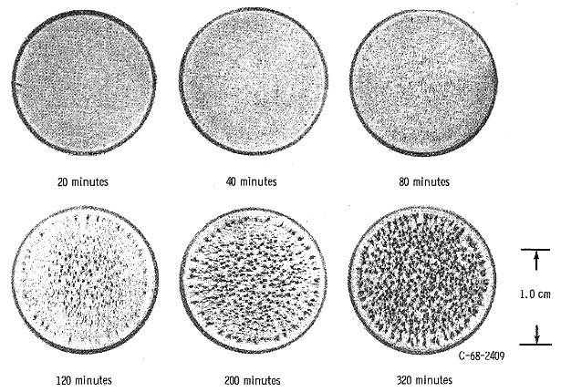
图 1 展示了空化冲蚀的典型发展过程(引自 Young,第 15 页;25 kHz,44.5 微米,24 °C 水)。与典型情况一样,冲蚀在边缘处最为强烈。Zhao[1](第 4 页)指出,这是因为边缘处的气泡比中心处的气泡更容易破裂。
|
|
|
在超声应用中,常常由超声变幅杆有意产生空化,以便观察其对工艺过程的影响(例如超声均质化)。然而,这种空化会逐渐从变幅杆端面上去除材料。这会引发几个问题。
- 随着端头变短,系统的频率会升高,直到电源无法再启动变幅杆。
- 随着变幅杆端面被冲蚀出凹坑,其产生的空化减少,从而影响工艺过程。
- 被冲蚀下来的材料可能污染工艺过程。
这些问题可以通过以下四种方法的组合来缓解 —
- 使用具有更高空化冲蚀抗力的变幅杆材料。
- 使用具有更高空化冲蚀抗力的涂层。
- 改善变幅杆的表面质量。
- 使用带可更换端头的变幅杆。
测试方法
超声空化冲蚀的测试方法由 ASTM 空化冲蚀规范 G32-10 规定。附录 A 给出了简要概述。
材料
金属
在涉及空化的应用中,钛(通常是 Ti-6Al-4V)往往是默认的谐振器材料。它具有可以接受(但并不出众)的空化冲蚀抗力,并且对许多液体也相对惰性。各种钢也有使用。(各种材料的空化冲蚀数据见附录 C。)
弹性体
弹性体不适合作为谐振器材料。不过,它们可用于阻止超声能量的传递,或用于减少空化冲蚀(主要是静止表面的空化冲蚀)。Knapp[1](第 370 页)指出,这些材料在相对较低强度的空化下可能表现出"完全没有空化损伤"。Light[1](第 45 页)发现,在 20 kHz、50 微米峰峰值振动下,硫化的三元乙丙橡胶(EPDM)板材的冲蚀抗力约为 316L 不锈钢的三倍。(注:未硫化的涂漆 EPDM 表现很差。)
可更换端头
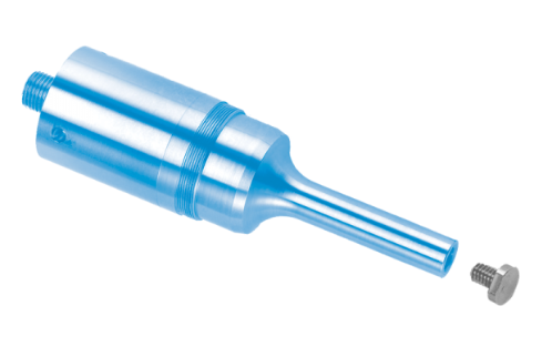
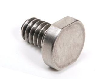
空化冲蚀使性能下降后,更换整个实体变幅杆的成本会很高。作为替代,对于在 20 kHz 下端面直径小于约 Ø25 mm 的变幅杆,可以使用可更换端头(有一定限制)。
|
||||||||||
|
|
涂层
已使用各种涂层来改善空化冲蚀性能(以钛作为参照)。这些涂层可以施加在端头上,也可以在以下场合使用:必须保留变幅杆基体材料(如钛)的场合、变幅杆端面面积太小或太大而无法安装可更换端头的场合,或者端面形状不规则的场合。涂层可按厚度分类:薄涂层或厚涂层;也可按延展性或脆性分类。
更多详细信息见 Zakrzewska[1](第 27 - 30 页)。
薄涂层
如果超声振动引起的惯性力相对较低,则可将涂层视为薄涂层。此时附着力不必很高。这类涂层包括铬和氮化钛。
硬铬
在其清洗槽换能器专利中,DeCastro[1](第 2 栏,第 25 行)断言,与 316L 不锈钢基体金属相比,2 mil(0.05 mm)的硬铬可将空化冲蚀降低 10 倍。DeCastro 将此归因于铬更高的硬度(60 Rc 对 25 Rc),尽管肯定还涉及其他因素。(DeCastro 既未说明试验程序,也未提供任何支持数据。另请注意,Bregliozzi 发现不锈钢的空化冲蚀高度依赖于材料的晶粒尺寸。)
氮化钛
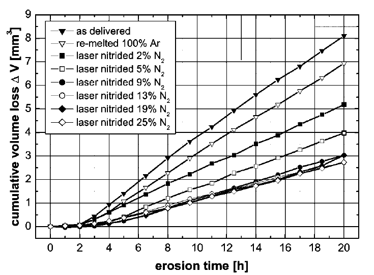
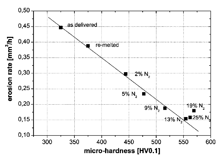
由于硬度高且附着性好,氮化钛长期以来一直被用于减少空化冲蚀。不过,该工艺不能随意应用。Kaspar[1] 研究了在氮-氩气氛中以不同氮气百分比在 Ti-6Al-4V 上激光沉积氮化钛。空化试验按照 ASTM G32-92 在 25°C 的去离子水中进行。空化由 20 kHz 的纵向振荡激发,振幅为 40 微米峰峰值,振动端头与静止试样之间的间距为 0.50 mm。图 5 和图 6 给出了结果。将氮气气氛提高到约 13%(显微硬度约 550)可持续降低空化冲蚀。在该水平下,冲蚀速率约为供货态钛的 1/3。然而,进一步提高氮气含量和硬度并不能进一步降低空化冲蚀。
|
|
|
|
|
|
Matsumura[1] 发现,即使氮化钛已被去除,由于残余应力的存在,基体材料仍具有改善的冲蚀抗力。
厚涂层
由于质量较大,厚涂层必须承受相当大的惯性力。此时涂层与基体材料之间附着力不足可能成为一个问题。如果这类涂层还是脆性的,则无法在大面积上应用(例如清洗槽),因为超声弯曲振动会导致其开裂。
蓝宝石
蓝宝石极其坚硬——莫氏硬度为 9.0,而金刚石为 10。然而,蓝宝石也非常脆。用蓝宝石抗空化冲蚀的效果似乎好坏参半。
Misonix[1](以其前身 Heat Systems 的名义)开发了一种将蓝宝石晶片粘接到实体变幅杆上的工艺。(第 8‑6 页)其文献声称,在空化应用中,蓝宝石晶片的寿命应为钛端头的 10 倍。
- 该蓝宝石为晶锭生长的合成材料。
- 晶片厚度为 1/16"。(第 4‑2 页)
- 晶片用剪切强度极高的环氧树脂粘接。然而,这种环氧树脂会受到空化冲蚀,并在强化学侵蚀下被浸出。由于蓝宝石是脆性的,任何可见的环氧树脂流失都会导致蓝宝石失效。
- 损坏或被冲蚀的晶片可在工厂更换。
一位了解 Misonix 工艺的知情人士报告 —
- 该蓝宝石为单晶。
- 该工艺最初是成功的,具有很高的冲蚀抗力。然而,在某个时候胶粘剂的配方显然发生了变化,导致了未指明的问题。
- 蓝宝石不能与可更换端头一起使用,因为拧紧过程中端头的变形(弯曲)会导致蓝宝石破裂。
此外,Sonics & Materials[1] 报告:"粘接蓝宝石和陶瓷端头的结果也很差。它们价格昂贵,并且会在几分钟内碎裂或脱落。"
Qsonica[1] 继承了 Misonix 的工艺。
银
Gunnerman 的专利 6,652,992 B1 [1] 声称,银(优选 99% 纯度)可以显著减少钛变幅杆(优选 99% 纯度但至少按重量计 85%)的超声空化冲蚀,尤其是在水性介质中。表 1 比较了银与不同钛的维氏硬度 HV。由于空化冲蚀抗力通常与硬度相关,而且 Gunnerman 未提供任何支持数据,他的冲蚀主张看来相当可疑。
|
||||||||||
|
表注 —
- 硬度值取自 matweb.com。
- 虽然 Gunnerman 指定 99% 纯钛作为优选的谐振器材料,但这种材料在实践中不太可能使用。实际应用最广泛的是 Ti-6Al-4V(退火态)。
附录 A. 材料的空化冲蚀测试
测试方法
超声空化冲蚀的测试方法由 ASTM 空化冲蚀规范 G32-10 规定。注:短横线后的数字(本例中为"10")指最后一次修订的年份。不过,之前的版本很可能大体相似。
在标准方法中,将待测材料的试样加工成端头并拧到超声变幅杆上。如果评估的是涂层,则将涂层施加在端头上。端头在液体(通常是水)中被激发振动,并测定空化速率。
也常使用另一种(非官方)方法。在这种"静止试样法"中,试样固定在静止平台上,振动的变幅杆端头置于其前方。来自变幅杆的空化随后作用于静止试样并使其冲蚀。遗憾的是,由于变幅杆-试样间隙没有标准化,各项研究的结果并不一致(ASTM G32-10,第 17 页)。
ASTM G32-10
以下是 ASTM 空化冲蚀规范 G32-10 的简要概述。完整信息请参阅该标准原文。
一般试验程序为 —
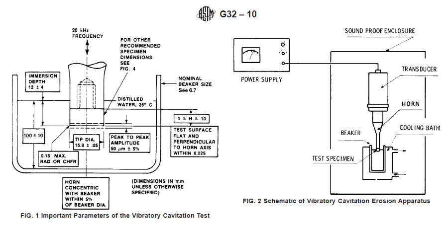
- 按图 A1 所示搭建试验设备。注意振幅按峰峰值规定。
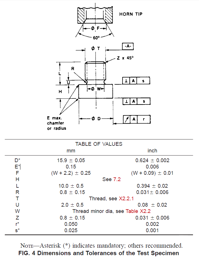
- 按图 A2 所示加工端头。
- 称量端头。
- 将端头浸入试验液体(通常是水,蒸馏水或去离子水)中并运行规定的时间。
- 取出端头,干燥,并仔细称量。
- 重复步骤 4 和 5,直到达到终止判据。例如,当平均冲蚀速率达到最大值并开始下降时,可以终止试验。
|
|
|
|
|
|
试验表面应先经轻切削加工,然后磨削和抛光至最大表面粗糙度 0.8 μm(32 μin.),加工方式应尽量减少表面损伤或变质。试样最后用 600 号砂布精整,得到 0.1 至 0.2 μm(4 至 8 μin.)rms 的表面粗糙度。(第 5‑6 页)
结果的报告
图 A3 展示了空化试验中典型的冲蚀阶段。
|
|
|
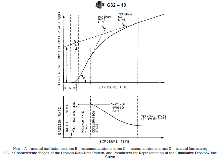
如图 A3 所示,空化冲蚀速率随时间并非常数,因此无法用单个数值完整表征,也不能由短期试验预测长期行为。ASTM G32-10(第 10 页)规定必须报告某些数值。
- 最大稳定冲蚀速率。这是初始孕育期之后的最大线性(或近线性)冲蚀速率,即图 A4 中"最大速率线"的斜率"B",通常以 μm/小时表示。
- 名义孕育时间。这是最大冲蚀速率线在时间轴上的截距(图 A4 中的数值"A")。
某些研究可能不符合 ASTM G32-10,此时可能报告其他结果。(在 ASTM G32-10 下这些可能是可选项。)
- 达到选定平均冲蚀深度(MDE)所需的时间。
- 选定暴露时间后的平均冲蚀深度(MDE)。然而,正如 ASTM G32-10 所指出的,"由于累积冲蚀-时间曲线的形状,在相同累积暴露时间后比较不同材料的质量损失或 MDE 是没有意义的。(原因是,对于抗蚀性很强的材料,所选时间可能仍处于孕育期或加速阶段,而对于脆弱的材料,同样的时间可能已处于最大速率阶段或减速阶段。)"
- 终止冲蚀速率。如果试验持续足够长的时间,这就是图 A4 中的斜率"C"。
结果的解读
当试验按照 ASTM G32-10 进行时,对于完全相同的材料,结果具有合理的可重复性。然而,名义上相同(宏观意义上)的材料在空化冲蚀下的实际表现可能差异很大。这可能是由于加工差异、晶粒尺寸不同等原因。Garcia[1](第 216 页)指出:"本实验室的经验是,取自不同炉次的所谓相同材料,其相关力学性能的差异可高达 50%。"
例如,图 A1 展示了在相同条件下试验 120 小时后,来自不同制造商的氮化硅("A"、"B"、"C"和"D")的空化冲蚀情况(Fatjo[1],第 12 页)。在该试验中,氮化硅"C"的材料损失是氮化硅"A"的 90 倍。
|
|
|
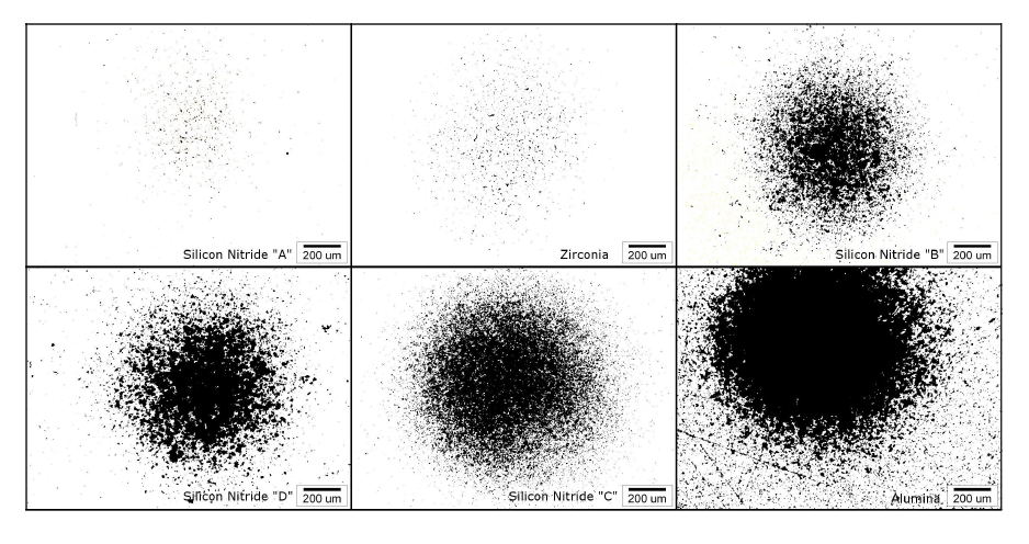
在其他研究中,可能违反了 ASTM G32-10 的某些规定(例如使用不同的端头尺寸、振幅、频率等),或者采用了不同的试验终止判据。此外,也可能选用不同的空化液体,例如海水的腐蚀作用可能加速空化冲蚀。这些问题意味着不同研究者之间的结果可能难以比较。
附录 B. 与空化冲蚀相关的参数
"尽管存在一些突出的矛盾之处,但总体趋势是:至少在相对相似的材料类别内,空化抗力通常随表面硬度、抗拉强度、屈服强度、延展性、断裂应变能等力学性能的提高而增大。然而,在不同类型材料之间会出现很大的反常,例如延展性金属与高强度脆性金属之间、金属与陶瓷之间、金属与弹性体之间等。"(Knapp[1],第 374 页)带参考文献的深入讨论见 Zakrzewska[1]。
硬度
硬度是与空化冲蚀抗力相关的主要材料性能。基体材料的硬度可以整体获得(例如通过整体淬硬),也可以局部获得(例如通过表面硬化或喷丸)。Zakrzewska[1](第 21 页)指出,空化抗力往往随硬度呈指数增长。
喷丸
Tomlinson[1] 在蒸馏水和 1% 盐水中对喷丸处理的 321 不锈钢(退火态)和纯铁进行了 20 kHz 空化试验。喷丸使材料加工硬化至 0.3 mm 深度(图 B1)。(选用 321 牌号不锈钢,部分原因可能是它对加工硬化响应良好。)规定的振幅为 15 μm(推测为峰峰值),水温为 50 °C。(在图 B1 中,"y"是试样表面以下的距离 [mm]。纵轴标注为"HV 0.02"。虽然 Tomlinson 未说明其含义,但它很可能指载荷为 0.1961 N 的维氏硬度标尺。参见维氏硬度计。)
|
|
|
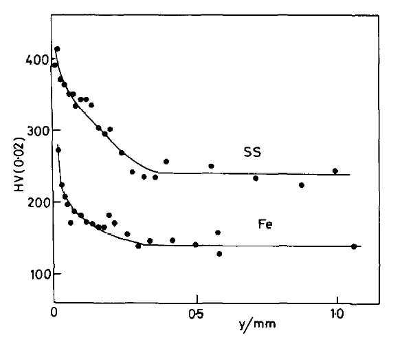
喷丸使蒸馏水中的稳定冲蚀速率降低了 5 倍,使盐水中的稳定冲蚀速率降低了 13 倍(Tomlinson 的表 1,第 238 页)。
疲劳强度
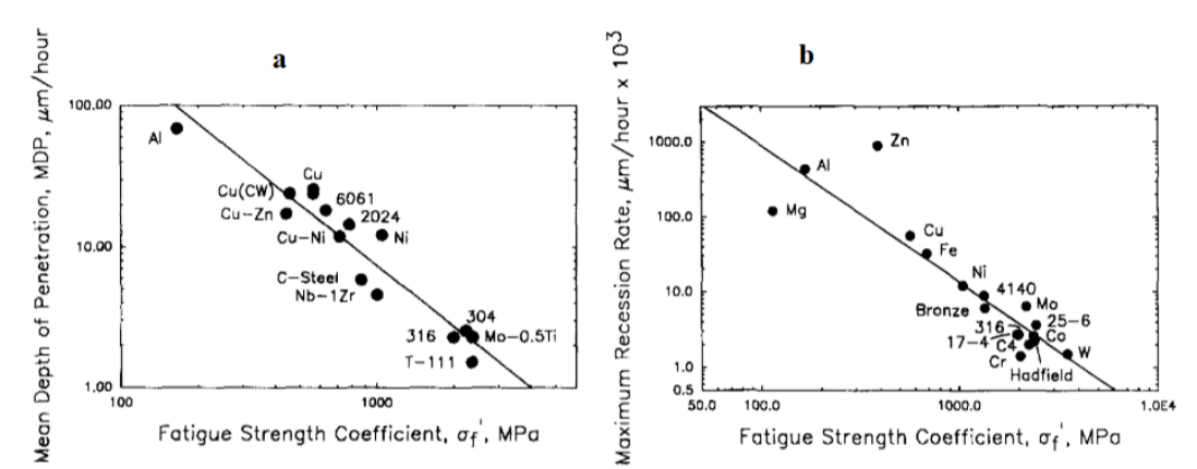
Zakrzewska[1](第 25 页)报道的研究表明,空化抗力与疲劳强度高度相关。
|
|
|
表面质量
当材料最初暴露于空化时,可能存在一个初始阶段,在此期间冲蚀速率与后续阶段相比可以忽略不计。如果表面经过高度抛光,这一孕育期可以延长。
晶粒尺寸
与疲劳一样,空化发生在微观尺度上。因此,两种宏观性能(如抗拉强度)几乎相同的材料,其空化冲蚀抗力可能有显著差异。Bregliozzi 关于晶粒尺寸对不锈钢 20 kHz 空化影响的研究说明了这一点。图 3 表明,在水中的空化抗力 Re 随晶粒尺寸减小和硬度提高而增大。(在图中,Re 的单位是小时/平均冲蚀穿透深度(以微米计)。pH 是水的酸碱性度量;"pH 7"为中性。)
|
|
|
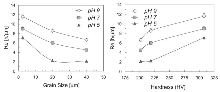
因此,除非精确规定材料的加工状态和微观特征,否则说材料 X 不如材料 Y 是不恰当的。(当然,这不适用于差异悬殊的材料。例如,就空化冲蚀而言,任何铝都不如任何钢。)
附录 C. 各种材料的空化冲蚀数据
以下信息仅供参考。由于损耗、疲劳、成本和/或材料可获得性等原因,所列的许多材料可能不适合用作超声变幅杆。例如,虽然许多钢的冲蚀速率低于钛,但它们的输出振幅受到内部损耗(发热)的限制。不过,通过优化轮廓以降低局部超声应力,可以改善这一发热问题。无论如何,其中一些材料仍可能适合用作可更换端头或涂层。
除特别注明外,以下数据均按照 ASTM G32-10 获得(见附录 A);具体为 —
- 空化流体为室温水。
- 振幅为 50 微米峰峰值。
Knapp / Garcia
下表引自 Knapp[1](第 425 页),他改编自 Garcia[1](表 13,第 130 页;表 14,第 140 页)。
- 数据按照 ASTM G32-10 在 20 kHz 下获得(见附录 A)。不过,端头直径为 13.9 mm(第 33 页),而非标准的 15.9 mm。
- MDP = 平均穿透深度 [mils] =(体积损失)/(试样端面面积)
- 1 mil = 25.4 μm
- 单晶钨的 MDP 为 0.025 mils/小时(表 29,第 201 页)。
- 除水试验外,还在高温铅铋合金、汞和锂中进行了空化试验。
- 还测试了其他材料。
Light
下图引自 Light[1](第 40 页)。
|
|
|
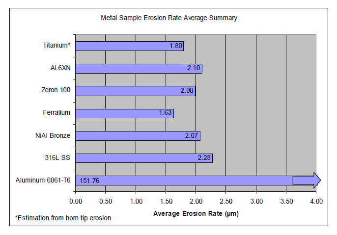
- 数据按照 ASTM G32-10 在 20 kHz 下获得(见附录 A)。不过,端头直径为 10.5 mm(第 65 页),而非标准的 15.9 mm。
- "冲蚀速率"指最大冲蚀速率,其定义为:最佳逼近 MDE(平均冲蚀深度)曲线(孕育期之后)线性(或近线性)最陡部分的直线斜率,以微米/小时表示。这就是图 A4 中"最大速率线"的斜率。
- 除钛以外,所有材料均采用"静止试样"法测试,即试样固定在液体容器内,振动的变幅杆端头靠近试样放置(本例中间距为 0.50 mm)。来自变幅杆的空化随后作用于静止试样并使其冲蚀。(第 27 页)
- 对于钛(Ti-6Al-4V,第 26 页),试样是连接在变幅杆末端的端头。由于这种方法与"静止试样"法对同一种材料可能给出不同结果,因此将钛的结果与其他结果进行比较可能并不恰当。(见 ASTM 空化冲蚀规范 G32‑10,第 3、17 页)
- 316L 不锈钢被用作参照材料,因为它常用于空化环境,包括涡轮叶片、阀门和管道部件。
- AL-6XN(UNS N08367)是一种奥氏体不锈钢,对氯化物点蚀(如海水)和其他强腐蚀环境具有很高的抗力。Knapp[1](第 351 页)指出:"空化与腐蚀相互促进是合乎逻辑的,因此由此产生的损伤往往远大于两者各自单独作用之和。"因此,与其他材料相比,这种材料(或类似材料)如果在腐蚀环境中测试,可能表现出相对更好的空化性能。
- Ferralium 是英格兰斯塔福德郡 Langley Alloys 公司生产的一种高强度耐腐蚀不锈钢。Zeron 100 是英格兰曼彻斯特 Weir Materials and Foundries 公司生产的类似牌号材料。
- NiAl 青铜(镍铝青铜——"NAB")。
钛
如果下面未指明钛的具体牌号,则推定为 Ti-6Al-4V(超声应用中最常用的牌号)。
Hielscher[1](第 6 页)报告,变幅杆在最大振幅下运行时,1000 小时内有 1 mm 被冲蚀。虽然变幅杆材料和试验振幅未明确说明,但上下文很可能表明材料是钛,振幅为 250 微米(推测为峰峰值)。(该试验未按照 ASTM G32‑10 进行。)
Elbert 的专利[1]称,"经热处理的钛被发现比普通退火钛的性能好得多。"(第 3 页,第 17 行)(Elbert 未说明"经热处理的钛"的含义,但这很可能指 STA(固溶处理并时效)状态。)事实上,Elbert 推测,用热处理钛制成的变幅杆寿命将比退火钛变幅杆高出两到三倍。(第 3 页,第 24 行)然而,鉴于 Elbert 未提供任何对比数据,而且 STA 钛仅比退火钛硬 13%(表 1),Elbert 推测的改进看来不太可能实现。
不锈钢
在对十二种不同不锈钢进行的蒸馏水 7 kHz 空化试验中,Bordeasu[1](第 5 页)发现,当铬含量与镍含量的比值约为 1.8:1 时,可获得最佳的空化冲蚀抗力。无论实际铬、镍含量如何,这一结论都成立。
Zakrzewska[1](第 27 页)报告,铁素体不锈钢比奥氏体和马氏体不锈钢更耐空化冲蚀(见其参考文献 45)。关于不锈钢的众多其他参考文献,请见 Zakrzewska。
另见图 B1a。
镍铝青铜(NAB)
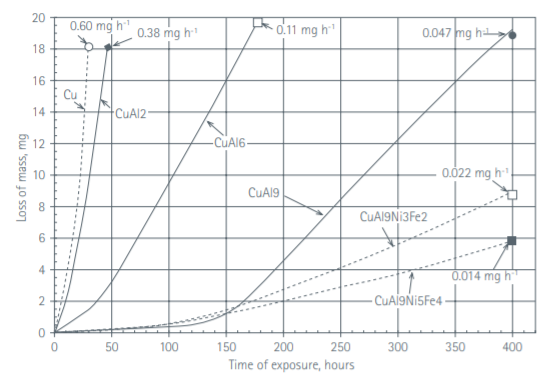
镍铝青铜(NAB)因其空化冲蚀抗力而常用于液体流动应用(如泵叶轮、船用螺旋桨等)(与钛和 316L 不锈钢大致相当;但请注意钛试验的注意事项)。
图 C2 展示了各种铜合金的空化速率。NAB 合金为虚线(右下方),其合金成分中含有镍。
|
|
|
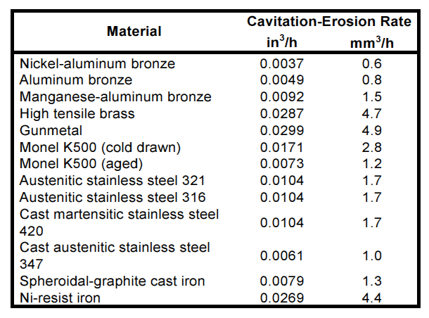
Callcut[1](第 16 页)的下表表明,NAB 的耐空化性能显著优于蒙乃尔合金和不锈钢。不过,合金成分和试验条件未予说明。
|
|
|
重要 — 铜和某些铜合金的损耗相对较高。因此,NAB 可能不适合作为谐振器材料,但可能适合作为涂层。
Cavitation erosion
Contents
- Overview
- Test methods
- Materials
- Replaceable tips
- Coatings
- Appendix A. Testing materials for cavitation erosion
- Appendix B. Parameters that correlate to cavitation erosion
- Appendix C. Cavitation erosion data for various materials
- Also see cavitation.
- Figures
- Figure 1. Cavitation erosion of nickel 270
- Figure 2a. Liquid processing horn with replaceable tip
- Figure 2b. Replaceable tip
- Figure 3. Cavitation erosion of Ti-6Al-4V without and with titanium nitride coatings
- Figure 4. Cavitation erosion rate of Ti-6Al-4V without and with titanium nitride coatings
- Figure A1. ASTM-G32 cavitation erosion test apparatus
- Figure A2. ASTM-G32 cavitation test specimen tip dimensions
- Figure A3. Stages of cavitation erosion
- Figure A4. Cavitation erosion of silicon nitride
- Figure B1. Effect of shot peening on surface hardness of 321 stainless steel (SS) and pure iron (Fe)
- Figure B1a. Effect of fatigue strength on resistance to cavitation erosion
- Figure B2. Effect of grain size and hardness on resistance to cavitation (Re)
- Figure C1. Cavitation erosion rates for various metals
Overview
Cavitation erosion occurs when a material is exposed to a cavitating fluid. The collapsing cavitation bubbles cause intense shock waves and microjets which, in turn, cause highly localized surface stresses. Repetition of this loading due to repeated bubble collapses causes local surface fatigue failure and the subsequent detachment or flaking off of pieces of material. (Brennen, section 3.6, p. 91)
Figure 1 shows the typical progression of cavitation erosion (from Young, p. 15; 25 kHz, 44.5 microns, 24 °C water). As is typical, the erosion is most intense at the edges. Zhao[1] (p. 4) indicates that this is because bubbles at the edges are more likely to burst than those at the center.
|
|
|
In ultrasonics the cavitation is often deliberately produced by an ultrasonic horn in order to see the effect on a process (e.g., ultrasonic homogenization). However, this cavitation gradually removes material from the face of the horn. This causes several problems.
- As the tip shortens, the frequency of the system increases until the power supply can no longer start the horn.
- As the horn face becomes pitted by erosion, it produces less cavitation which thereby impacts the process.
- The eroded material may contaminate the process.
These problems can be mitigated by a combination of four approaches —
- Use a horn material that has higher cavitation erosion resistance.
- Use a coating that has higher cavitation erosion resistance.
- Improve the horn's surface finish.
- Use a horn with a replaceable tip.
Test methods
The test method for ultrasonic cavitation erosion is specified by ASTM cavitation erosion specification G32-10. Appendix A gives a brief overview.
Materials
Metals
Titanium (typically Ti-6Al-4V) is often the default resonator material for applications involving cavitation. It has acceptable (but not exceptional) cavitation erosion resistance and is also relatively inert to many liquids. Various steels are also used. (See Appendix C for cavitation erosion data for various materials.)
Elastomers
Elastomers are not suitable as resonator materials. However, they may be useful to prevent transmission of ultrasonic energy or to reduce cavitation erosion (mainly of stationary surfaces). Knapp[1] (p. 370) indicates that these materials may show "no cavitation damage at all" under relatively low-intensity cavitation. Light[1] (p. 45) found that vulcanized Ethylene Propylene Diene Monomer (EPDM) sheet had about three times better erosion resistance than 316L stainless steel when exposed to 50 micron peak-to-peak vibration at 20 kHz. (Note: painted EPDM, which was nonvulcanized, performed poorly.)
Replaceable tips
An entire solid horn would be expensive to replace after cavitation erosion had degraded its performance. Instead, replaceable tips can be used (with limitations) with horns whose face diameters are less than about Ø25 mm at 20 kHz.
|
||||||||||
|
|
Coatings
Various coatings have been used to improve cavitation erosion (compared to titanium as a reference). These coatings can be applied to tips but can also be used where the base horn material must be preserved (e.g., titanium), where the horn's face area is too small or too large to accept a replaceable tip, or where the face is irregular. Coatings can be classified according to their thicknesses: thin or thick. They can also be classified according to whether they are ductile or brittle.
See Zakrzewska[1] (pp. 27 - 30) for extensive information.
Thin coatings
Coatings can be considered thin if the inertial forces due to the ultrasonic vibration are relatively low. Then the adhesion force does not have to be high. These coatings include chrome and titanium nitride.
Hard chrome
In his cleaning tank transducer patent, DeCastro[1] (column 2, line 25) asserts that 2 mil (0.05 mm) hard chrome reduces cavitation erosion by a factor of 10 compared to the 316L stainless steel base metal. DeCastro attributes this to the higher hardness of the chrome (60 Rc versus 25 Rc) although other factors may certainly be involved. (DeCastro does not specify the test procedure nor provide any supporting data. Also note that Bregliozzi found that cavitation erosion of stainless steel is highly dependent on the material's grain size.)
Titanium nitride
Because of its hardness and good adhesion, titanium nitride has long been used to reduce cavitation erosion. However, the process can't be applied arbitrarily. Kaspar[1] investigated laser deposited titanium nitride on Ti-6Al-4V for various percentages of nitrogen in a nitrogen-argon atmosphere. The cavitation tests were conducted according to ASTM G32-92 in deionized water at 25°C. Cavitation was induced by 20 kHz longitudinal oscillation at 40 microns peak-to-peak with a standoff distance of 0.50 mm between vibrating tip and the stationary sample. Figures 5 and 6 show the results. Increasing the nitrogen atmosphere up to about 13% (micro-hardness ~550) steadily reduces the cavitation erosion. At that level the erosion rate is about 3x lower than the as-delivered titanium. However, further increases in nitrogen and hardness don't further reduce the cavitation erosion.
|
|
|
|
|
|
Matsumura[1] has found that even when the titanium nitride has been removed, the base material still has improved erosion resistance due to the remaining residual stress.
Thick coatings
Due to their mass, thick coatings must resist substantial inertial forces. Then inadequate adhesion between the coating and the base material can be a problem. If such coatings are also brittle then they cannot be applied over a large area (e.g., cleaning tanks) because the ultrasonic flexure will cause them to crack.
Sapphire
Sapphire is extremely hard — 9.0 on the Mohs scale where diamond is 10. However, sapphire is also very brittle. The results of using sapphire against cavitation erosion seem to be mixed.
Misonix[1] (under its predecessor Heat Systems) developed a process for bonding a sapphire wafer to a solid horn. (p. 8‑6) Their literature claims that the sapphire wafer should last 10 times longer than a titanium tip in cavitation applications.
- The sapphire is boule-grown synthetic.
- The wafer is 1/16" thick. (p. 4‑2)
- The wafer is bonded with an extremely high shear epoxy. However, this epoxy is subject to cavitation erosion and leaching under strong chemical attack. Because sapphire is brittle, any visible loss of epoxy will cause the sapphire to fail.
- Damaged or eroded disks can be replaced at the factory.
A source with knowledge of Misonix' process reported —
- The sapphire was a single crystal.
- The process was initially successful and gave high erosion resistance. However, at some point the formulation of the adhesive apparently changed which caused unspecified problems.
- Sapphire could not be used with a replaceable tip because distortion (bending) of the tip during tightening caused the sapphire to fracture.
Also, Sonics & Materials[1] reports, "Results with affixation of sapphire and ceramic tips have also been poor. They are expensive and shatter or separate within minutes."
Qsonica[1] has inherited Misonix' process.
Silver
Gunnerman's patent 6,652,992 B1 [1] claims that silver (preferably 99% pure) can significantly reduce the ultrasonic cavitation erosion of a titanium horn (preferably 99% pure but at least 85% by weight), particularly in aqueous media. Table 1 compares the Vickers hardness HV of silver to different titaniums. Since cavitation erosion resistance is typically related to hardness and since Gunnerman presents no supporting data, his erosion claims seem rather dubious.
|
||||||||||
|
Table notes —
- Hardness values are from matweb.com.
- Although Gunnerman specifies 99% pure titanium as the preferred resonator material, this material is unlikely in practice. Instead, Ti-6Al-4V (annealed) is most widely used.
Appendix A. Testing materials for cavitation erosion
Test methods
The test method for ultrasonic cavitation erosion is specified by ASTM cavitation erosion specification G32-10. Note: the number after the dash ("10" in this case) refers to the year of the last revision. However, previous versions are likely to be substantially similar.
In the standard method, a test specimen of the desired material is machined as a tip and screwed to an ultrasonic horn. If a coating is being evaluated then the coating is applied to the tip. The tip is activated in a liquid (typically water) and the rate of cavitation is determined.
An alternate (unofficial) method is often used. In this "stationary specimen method" the test specimen is attached to a stationary platform and the vibrating horn tip is placed in front of it. The cavitation from the horn then acts to erode the stationary specimen. Unfortunately, various findings show inconsistent results because the horn-specimen gap has not been standardized (ASTM G32-10, p. 17).
ASTM G32-10
The following is a brief overview of ASTM cavitation erosion specification G32-10. See that source for complete information.
The general test procedure is —
- Set up the test equipment as shown in figure A1. Note that the amplitude is specified as peak-to-peak.
- Machine the tips as shown in figure A2.
- Weigh the tip.
- Immerse the tip in the test liquid (often water, distilled or deionized) and run for a specified time.
- Remove the tip, dry the tip, and carefully weigh it.
- Repeat steps 4 and 5 until a termination criterion has been reached. For example, the test may be terminated when the average rate of erosion has reached a maximum and begins to diminish.
|
|
|
|
|
|
The test surface should be lightly machined, then ground and polished to a maximum surface roughness of 0.8 μm (32 μin.) in such a way as to minimize surface damage or alteration. The specimen is finished with 600 grit emery cloth, yielding a surface finish of 0.1 to 0.2 μm (4 to 8 μin.) rms. (pp. 5‑6)
Reporting the results
Figure A3 shows typical erosion stages in a cavitation test.
|
|
|
As figure A3 shows, cavitation rate of erosion is not constant with time so it cannot be fully characterized by a single number, nor can long-term behavior be predicted from a short-term test. ASTM G32-10 (p. 10) specifies that certain values must be reported.
- Maximum stable rate of erosion. This is the maximum linear (or near linear) erosion rate after the initial incubation period. This is the slope "B" of the "maximum rate line" of figure A4, typically expressed in μm/hour.
- Nominal incubation time. This is intercept of the maximum erosion rate line on the time axis (the value "A" of figure A4).
Some investigations may not confrom to ASTM G32-10 in which case other results may be reported. (These may be optional under ASTM G32-10.)
- Time to achieve a chosen mean depth of erosion (MDE).
- Mean depth of erosion (MDE) after a chosen exposure time. However, as ASTM G32-10 notes, "Because of the shape of the cumulative erosion-time curve, it is not meaningful to compare the mass loss or MDE for different materials after the same cumulative exposure time. (The reason is that a selected time may still be within the incubation or acceleration stage for a very resistant material, whereas for a weak material the same time may be within the maximum rate or deceleration stage.)"
- Terminal erosion rate. This is the slope "C" in figure A4 if the test has continued for a sufficiently long time.
Interpreting the results
When tests are performed according to ASTM G32-10 the results are reasonably repeatable for identical materials. However, materials that are nominally identical (in a macro sense) may actually may perform very differently when exposed to cavitation erosion. This may be due to processing differences, differing grain sizes, etc. Garcia[1] (p. 216) notes, "It is the experience of this laboratory that supposedly identical materials taken from different heats may have variations in applicable mechanical properties as great as 50%."
For example, figure A1 shows cavitation erosion of silicon nitride ("A", "B", "C" and "D") from different manufacturers after 120 hours, all tested under the same conditions (Fatjo[1], p. 12). For this test the material loss from silicon nitride "C" was 90 times greater than for silicon nitride "A".
|
|
|
In other investigations certain specifications of ASTM G32-10 may have been violated (e.g., using a different tip size, amplitude, frequency, etc.) or differing test termination criteria may have been used. Also, different cavitation liquids may be chosen where, for instance, the corrosive effects of sea water may accelerate the cavitation erosion. These problems mean that comparison of results among various investigators may be difficult.
Appendix B. Parameters that correlate to cavitation erosion
"Although there are some outstanding discrepancies, the tendencies are that cavitation resistance generally increases with increasing mechanical properties such as surface hardness, tensile strength, yield strength, ductility, strain energy to failure, etc., at least within groupings of relatively similar materials. However, large anomalies occur betweein different types of materials such as ductile metals versus strong brittle metals, metals versus ceramics, metals versus elastomerics, etc." (Knapp[1], p. 374) See Zakrzewska[1] for a good discussion with references.
Hardness
Hardness is the primary material property that correlates with cavitation erosion resistance. Hardness in the base material can be produced globally (e.g., by through hardening) or locally (e.g., by surface hardening or shot peening). Zakrzewska[1] (p. 21) indicates that cavitation resistance often increases exponentially with hardness.
Shot peening
Tomlinson[1] conducted 20 kHz cavitation tests on shot peened 321 stainless steel (annealed) and pure iron in distilled water and 1% salt water. The shot peening work hardened the materials to a depth of 0.3 mm (figure B1). (Grade 321 stainless steel may have been chosen, in part, because it responds well to work hardening.) The specified amplitude was 15 μm (presumably peak-to-peak) and the water temperature was 50 °C. (In figure B1 "y" is the distance below the specimen's surface [mm]. The vertical axis is labeled as "HV 0.02". Although Tomlinson doesn't specify the meaning, it likely refers to the Vickers hardness scale with a load force of 0.1961 N. See Vickers Hardness Tester.)
|
|
|
Shot peening reduced the stabilized erosion rate by a factor of 5 in the distilled water and a factor of 13 in the salt water (Tomlinson's table 1, p. 238).
Fatigue strength
Zakrzewska[1] (p. 25) reports on research that shows that cavitation resistance is highly correlated to fatigue strength.
|
|
|
Surface finish
When a material is initially exposed to cavitation, there may be an initial stage during which the erosion rate is negligible compared to later stages. This incubation period can be extended if the surface is highly polished.
Grain size
Like fatigue, cavitation occurs on a microscopic scale. Thus, two materials that have nearly identical macroscopic properties (e.g., tensile strength) may have significantly different resistance to cavitation erosion. This is illustrated by Bregliozzi's research into the effect of grain size on 20 kHz cavitation of stainless steels. Figure 3 shows that the cavitation resistance Re in water increases with smaller grain size and hardness. (In the graphs, Re has units of hours per mean depth of erosion penetration (measured in micro-meters). pH is the measure of the acidity or basicity of the water; "pH 7" is neutral.)
|
|
|
Thus, it is not proper to say that material X is inferior to material Y unless the processing and microscopic characteristics of the materials are precisely specified. (Of course this doesn't apply to materials that are grossly different. For instance, any aluminum will be inferior to any steel for cavitation erosion.)
Appendix C. Cavitation erosion data for various materials
The following information is provided for reference. Many of the listed materials may not be suitable as ultrasonic horns because of loss, fatigue, cost, and/or material availability. For example, although many steels have lower erosion rates than titanium, their output amplitudes are limited by internal losses (heating). However, this heating problem can be improved with an optimized profile that reduces the local ultrasonic stress. In any case, some of the materials might still be suitable as replaceable tips or coatings.
Where noted, the following data were obtained in accordance with ASTM G32-10 (see Appendix A); specifically —
- The cavitating fluid is room-temperature water.
- The amplitude is 50 microns peak-to-peak.
Knapp / Garcia
The following table is from Knapp[1] (p. 425) who adapted it from Garcia[1] (table 13, p. 130; table 14, p. 140).
|
||||||||||||||||||||||||||||||||||||||||||||||||||
|
- The data were obtained in accordance with ASTM G32-10 at 20 kHz (see Appendix A). However, the tip diameter was 13.9 mm (p. 33) rather than the standard 15.9 mm.
- MDP = mean depth of penetration [mils] = (volume loss) / (specimen face area)
- 1 mil = 25.4 μm
- The MDP for single crystal tungsten was 0.025 mils/hour (table 29, p. 201).
- In addition to water tests, cavitation tests were also conducted in high temperature lead-bismuth, mercury, and lithium.
- Other materials were also tested.
Light
The following chart is from Light[1] (p. 40).
|
|
|
- The data were obtained in accordance with ASTM G32-10 at 20 kHz (see Appendix A). However, the tip diameter was 10.5 mm (p. 65) rather than the standard 15.9 mm.
- The "erosion rate" is the maximum rate of erosion which is defined as the slope of the straight line that best approximates the linear (or nearly linear) steepest portion of the MDE (mean depth of erosion) curve (occurring after the incubation period) and is expressed in micrometers per hour. This is the slope of the "maximum rate line" of figure A4.
- With the exception of titanium, all materials were tested by the "stationary specimen" method whereby the specimen was fixed within the liquid container and the vibrating horn tip was placed close to it (0.50 mm in this case). The cavitation from the horn then acted to erode the stationary specimen. (p. 27)
- For titanium (Ti-6Al-4V, p. 26) the test specimen was a tip attached to the end of the horn. Since this method and the "stationary specimen" method may give different results for the same material, it may not be proper to compare the titanium results to the other results. (See ASTM cavitation erosion specification G32‑10, pp. 3, 17)
- 316L stainless steel was used as a reference material since it is often used in cavitating environments including turbine blades, valve and piping components.
- AL-6XN (UNS N08367) is an austenitic stainless steel that has high resistance to chloride pitting (e.g., sea water) and other very corrosive environments. Knapp[1] (p. 351) notes, "It is logical that cavitation and corrosion should be mutually reinforcing so that the resulting damage is often much greater than the sum of the two, if each acted alone." Thus, compared to other materials this material (or similar) might exhibit relatively better cavitation performance if tested in a corrosive environment.
- Ferralium is a high strength, corrosion resistant stainless steel produced by Langley Alloys of Staffordshire England. Zeron 100 is a similar grade of material produced by Weir Materials and Foundries in Manchester England.
- NiAl bronze (Nickel Aluminum Bronze — "NAB").
Titanium
If the specific grade of titanium is not specified below then it is presumed to be Ti-6Al-4V (most commonly used in ultrasonic applications).
Hielscher[1] (p. 6) reports that 1 mm of the sonotrode erodes within 1000 hours when operated at maximum amplitude. Although the sonotrode material and test amplitude are not explicitly stated, the accompanying text likely indicates that the material is titanium and the amplitude is 250 microns (presumably peak-to-peak). (This test was not conducted according to ASTM G32‑10.)
Elbert's patent[1] states that, "heat treated titanium was found to perform much better than regular annealed titanium." (p. 3, line 17) (Elbert doesn't specify the meaning of "heat treated titanium" but this is likely the STA (solution treated and aged) condition.) In fact, Elbert speculates that horns made of the heat treated titanium would provide two to three times more life than those made of annealed titanium. (p. 3, line 24) However, given that Elbert doesn't provide any comparative data and that STA titanium is only 13% harder than annealed titanium (table 1), Elbert's speculative improvements seem unlikely.
Stainless steel
In 7 kHz cavitation tests on twelve different stainless steels in distilled water, Bordeasu[1] (p. 5) found that optimum resistance to cavitation erosion occurs when the ratio of chrome to nickel content is approximately 1.8:1. This was true regardless of the actual chrome or nickel content.
Zakrzewska[1] (p. 27) reports that ferritic stainless steel resists cavitation erosion better than austenitic and martensitic stainless steel (see reference 45 there). See Zakrzewska for numerous other references to stainless steel.
Also see figure B1a.
Nickel-aluminum bronze (NAB)
Nickel-aluminum bronze (NAB) is often used in liquid flow applications (e.g., pump impellers, ship propellers, etc.) because of its resistance to cavitation erosion (approximately comparable to titanium and 316L stainless steel; however, see note of caution for the titanium tests).
Figure C2 shows the cavitation rates for various copper alloys. The NAB alloys are the dashed lines (lower right) whose alloys contain nickel.
|
|
|
The following table from Callcut[1] (p. 16) indicates that NAB resists cavitation significantly better than monels and stainless steels. However, the alloy compositions and test conditions weren't stated.
|
|
|
Important — Copper and some copper alloys have relatively high loss. Thus, NAB might not be suitable as a resonator material but might be suitable as a coating.