端头(可更换式)
引言
可更换端头安装在谐振器输出端附近。在下列情况下它可能很有用 ——
- 原型试制。在塑料点焊或铆接中,变幅杆端面的最佳轮廓可能尚未确定。此时可以尝试不同轮廓的原型端头,而无需加工整个定制变幅杆。
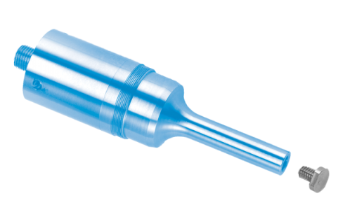
- 磨损。变幅杆端面会因磨蚀、空化冲蚀或冲击而磨损或变形。这种磨损会导致频率、振幅和应用方面的问题(见下文)。发生此类磨损后,更换整体式实心变幅杆的成本很高。此时可以使用消耗性端头(见图 1)。但是,如果可靠性是首要考虑(例如大批量应用,尤其是需要避免停机的场合),那么定制实心变幅杆可能更为理想。这时可以在变幅杆输出表面镀铬、镀碳化物或镀氮化钛,以提高耐磨性。(Dukane[1],第 6 页)不过,这些镀层对空化冲蚀可能并不奏效。
根据连接方式,端头可分为三类 ——
- 螺纹连接
- 夹紧连接
- 过盈配合
螺纹连接
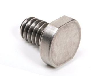
螺纹端头通过其一体式螺纹螺柱固定在谐振器上。图 1是一个示例。
|
||||||||||
|
|
局限性
材料
Dukane[2],第 63 页 —— "需要特别注意的是,可更换端头和螺纹变幅杆都必须用钛制成。不应使用任何其他材料。"否则,由于"材料密度不同"(当变幅杆材料指定为钛时),可能会导致"发热"。(第 105 页)
这一限制的原因尚不清楚,因为变幅杆和端头似乎完全可以用钢制造。另外,混用不同材料(例如钛变幅杆配钢端头)的影响也不明确,但另一份报告(来源不详)也有类似说法:"端头和工具不应使用同一种合金,否则容易发生咬粘。"需要指出的是,钢端头经常与钛金属焊接变幅杆配合使用,不过此时端头是用螺母固定,而不是直接拧入变幅杆(图 2)。(参见金属焊接端头。)
电偶腐蚀
对于液体处理应用,端头通常用钛制造,因为钛相对惰性,且对空化冲蚀具有较好的抵抗力。不锈钢端头也具有类似的优点,在某些情况下可能更为可取。当不锈钢端头与钛变幅杆配合使用时,可能需要关注电偶腐蚀问题。
Serhan[1A]研究了外科植入物中钛-钛接头和钛-不锈钢接头的电偶腐蚀。钛材为 Ti-6Al-4V;不锈钢为 316 L。这些材料在生理盐水中以 5 Hz 的频率经受五百万次微动循环。他得出结论:"本研究的结果表明,在钛合金-不锈钢混合脊柱植入物结构中,电偶腐蚀不起显著作用。"(第 386 页)Hoi[1A]对工业纯(cp)钛与 316 L 不锈钢之间的相互作用也得出了类似的结论。
空化冲蚀
如果空化冲蚀是个问题,请参阅此处。
重量与振幅
端头在重量和振幅上存在限制,以约束作用在端头螺纹、变幅杆螺纹以及端头-变幅杆接头上的惯性力。在 20 kHz 下,端头最大直径通常限制在约 Ø25 mm。最小的端头允许最高的振幅。
|
||||||||||||||||||||||||||||||||||||||||||||||||||||||||||||||||||||||||||||||||||||
|
表格注释 ——
- 质量数据针对平端面端头,且包含螺纹柄部。不过,其他端头(例如铆接端头、点焊端头)可能也应符合这些数据。
- 参考文献 ——
- Branson ——
- 质量 —— Branson[7](第 24 页)
- 力矩 —— Branson[3](第 2 页)
- Dukane[1],第 11 页
- Qsonica[1](第 1 页) —— Qsonica 给出的振幅是针对 20 kHz 液体处理的。这些振幅可能由系统的机械设计(变幅杆的输入振幅和变幅杆的增益)决定,而不是由性能要求(端头发热、端头或变幅杆疲劳、界面咬粘等)决定。
- Sonics & Materials[2](第 13 页)
- Branson ——
施加载荷
除惯性力外,某些端头还会承受来自应用本身的载荷。例如,金属焊接会对端头施加很高的剪切力(图 2)。
与有机溶剂或低表面张力液体配合使用
对于图 1 所示类型的端头,业界似乎有一个共识:如果端头将浸没在有机溶剂或低表面张力液体中,就不应使用可更换端头。例如,Sonics & Materials[3](第 2 页)指出:"有机溶剂(如二氯甲烷)或低表面张力液体会渗入探头与可更换端头之间的界面,从而将颗粒带入螺纹部分,并使端头与探头隔离。处理含有有机溶剂或低表面张力液体的样品时,务必使用整体式探头。切勿使用带可更换端头的探头。"
Berliner Ultrasonics认为,某些溶剂的问题在于它们容易渗入端头-变幅杆界面之下,从而导致空化冲蚀或被流体中的颗粒磨损。据推测,这种渗吸之所以发生,是因为在变幅杆行程的收缩阶段,端头上的惯性力会使端头-变幅杆界面的边缘张开一个小缝隙(即端头发生"拍动"),从而使流体和颗粒得以进入。据称,大直径端头的这一问题更为严重。
解决方案
- 用整体式半波长或全波长延长变幅杆替换端头。
- 在变幅杆端面(螺纹孔旁)或端头后界面(螺柱旁)加工一个浅台阶,使端头与变幅杆仅在界面边缘的一个小环形区域接触。这样做有两个好处 ——
- 由于界面接触面积减小,相同的拧紧力矩会增大界面接触压力。
- 由于仅在界面边缘接触,拍动现象基本得以消除。
- 在变幅杆-端头接头处使用 O 形圈。Culp[0]曾在熔融焊料中对端头进行空化冲蚀试验时成功使用过这种方法。
可更换端头的翻新
发生显著磨损后,可更换端头有时可以通过对磨损表面进行再加工来翻新。应考虑以下几点。
- 频率。去除被冲蚀的材料后,超声叠堆的频率会升高。超声电源(发生器)通常有一个能够正常工作的频带,具体取决于电源的设计。不过,这个频带通常至少为标称工作频率的 \( \pm \)1%(例如 20 kHz 时为 \( \pm \)200 Hz)或更宽。设备制造商可以提供确切的规格,尽管设备在规定频带之外也可能正常工作。端头可以反复翻新,直到频率超出这一频带为止;此时由于电源内部保护电路的作用,电源将无法再启动。
- 振幅。随着频率升高,输出振幅可能发生变化。如果振幅很关键,应在端头全新时进行测量以建立基准。之后安装翻新端头时,应通过电源调节振幅,使其恢复到基准振幅。这些测量可以在空气中进行。
- 发热。新端头应能在空气中运行一段时间(至少 30 秒)而不出现明显发热。如果翻新后的端头出现明显发热,说明去除的材料过多,端头表面的刚度已不足以承受拧紧载荷。此时应将翻新端头报废。
为预留更多磨损余量,端头最初可以加工得比正常长度略长一些。此时频率会低于标称值(例如为 19.8 kHz 而非 20 kHz)。但是,增加的重量会给端头-变幅杆接头带来额外的应力,因此如果该接头出现任何额外发热,就应避免采用这种方法。
翻新间隔(空化冲蚀)
如果平端面端头受到空化冲蚀,则应在冲蚀变得过度之前进行翻新。否则,由于空化凹坑内滞留气泡,端头的效能会降低。
Sonics & Materials[4](第 16 页)建议每五到六小时检查一次端头的空化冲蚀情况,必要时进行抛光。当然,这一检查/抛光间隔取决于具体工况。
装配
润滑剂
Dukane[1](第 11 页)建议 ——
- 在端头与变幅杆配合的表面上涂抹一薄层 Dow-Corning #4 高温高压硅脂(或改用 #111)。
- 如果不能使用硅基润滑脂,可以使用石油基润滑脂。不过,它可能会在表面留下碳质沉积物,从而需要更频繁地维护接头。
- 不要在端头螺纹上涂抹任何润滑脂。
最后一条建议的原因尚不清楚。可能是因为某些润滑剂最终会污染螺纹或使螺纹发生空化,从而导致端头难以拆卸。不过,使用干性润滑剂(例如 Teflon – PTFE)可以避免这一问题。
如果端头会接触食品,则润滑剂必须获得相关批准。在这种情况下,整体式变幅杆可能比带可更换端头的变幅杆更为可取。
拧紧力矩
对于同一款端头,表 1显示 Dukane 推荐的拧紧力矩明显高于 Branson。其原因尚不清楚。
一般注意事项
螺纹受力方向
如果端头通过螺纹紧固件直接固定到变幅杆上,则螺纹必须沿变幅杆振动方向布置(例如见图 1 和图 2)。这将使螺纹承受拉力。如果螺纹与变幅杆振动方向垂直,则螺纹将承受剪切。在这种情况下,作用在端头上的惯性力和载荷对螺纹来说过大,无法抵抗。这将导致端头在端头-变幅杆界面处滑移,从而在该处发热,并很可能导致紧固件失效。 (如果振幅足够小,这条建议或许可以忽略。不过,在那种情况下,通常也不需要用可更换端头来对抗磨损。)
夹紧连接
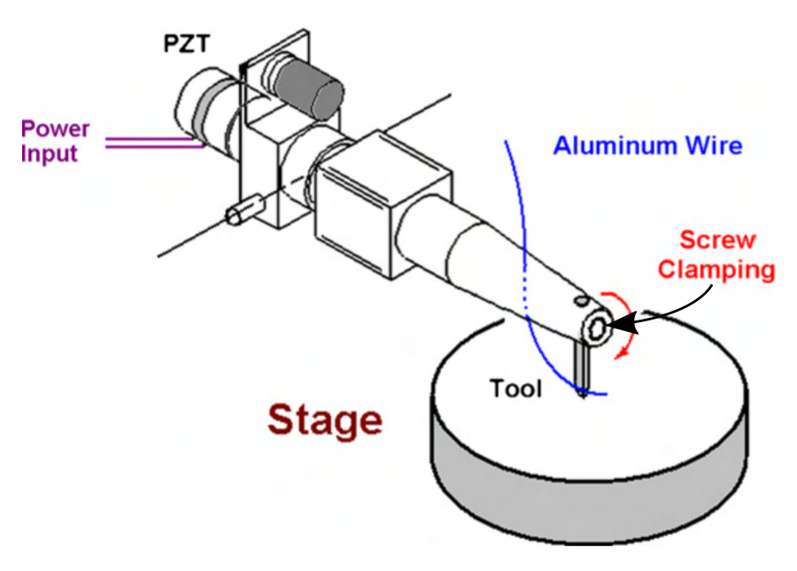
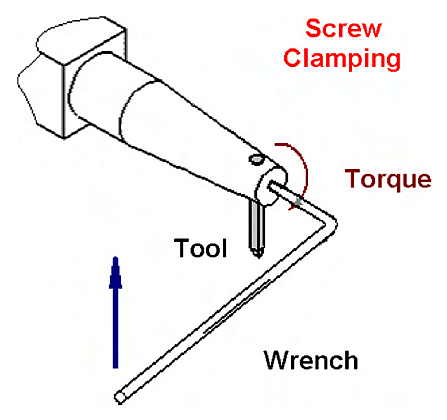
在夹紧连接中,端头通过端头本体之外的某种方式固定。例如,可以通过螺母(图 2)、夹紧环(图 X)、紧定螺钉(图 4)、螺钉(图 3)等方式固定。
|
|
|
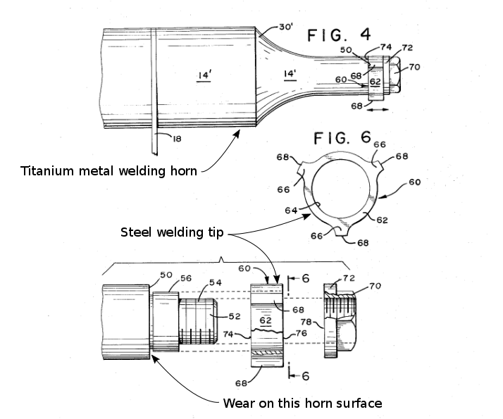
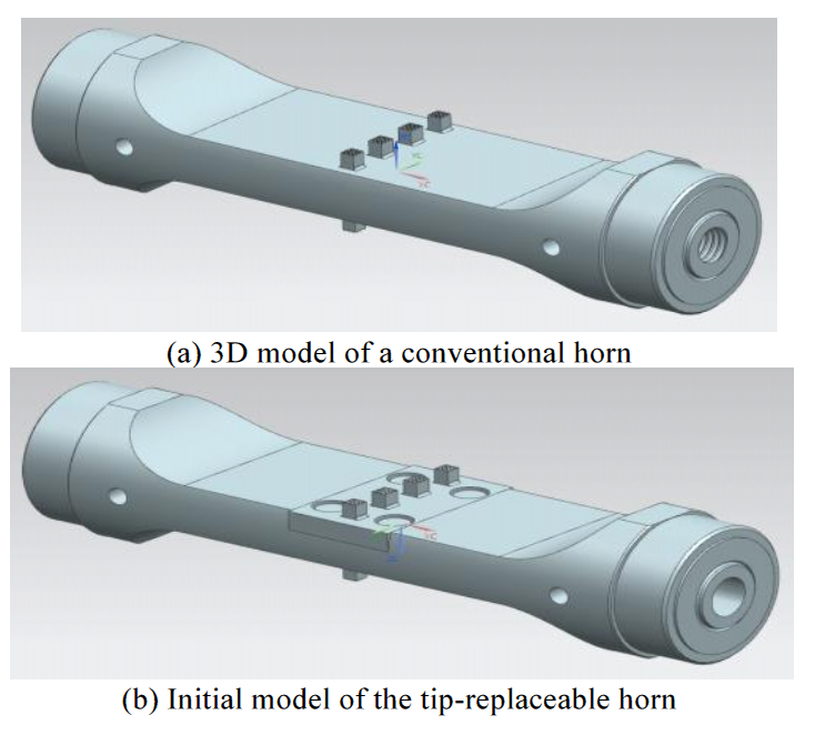
图 3b(Kim[1])展示了一种金属焊接变幅杆的提议设计,其中可更换端头(中间的矩形部分)由四个横向螺钉固定。尽管有限元分析表明这一设计可能可行,但它在实际应用中无疑会失败,原因是螺纹为横向布置,而且端头相对于变幅杆过大(导致惯性载荷很高)。
|
|
|
|
||||||||||
|
过盈连接
过盈连接可以通过锁紧锥面配合或压配合实现。
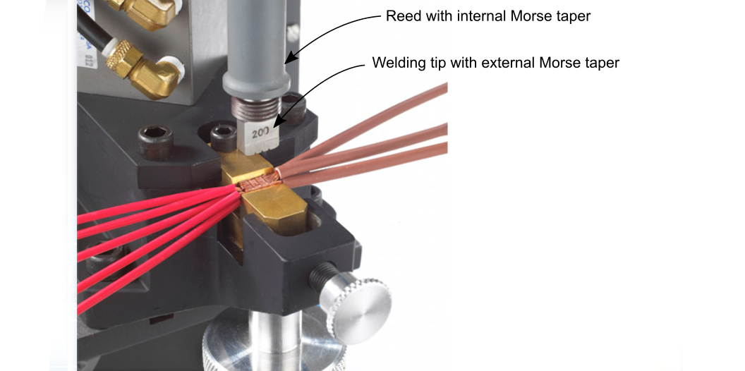
Sonobond 的 Wedge-Reed 金属焊机采用带浅锁紧锥面(莫氏锥度)的端头,该锥面与振动簧片自由端上相匹配的锥孔配合(图 5)。端头上图示的螺纹并不与簧片啮合;相反,它们用于通过顶出螺母拆卸端头。
|
|
|
Culp[0]曾在横向驱动金属焊机中使用锥形销作为焊接端头。锥形销插入变幅杆上相匹配的铰孔中。这一设计取得了一定的成功,但由于焊接过程中的高剪切力,接头最终发生退化。这一设计后来被图 2的可更换端头所取代,后者更可靠、更通用(可通过多个焊接凸角方便地调整方向)。
Tips (replaceable)
Contents
- Introduction
- Threaded attachment
- Clamped attachment
- Interference attachment
- Figures
- Tables
- Table 1. Standard 20 kHz flat-faced tips
Introduction
A replaceable tip is attached near the output end of a resonator. It may be useful in the following circumstances —
- Prototyping. In plastic spot welding or staking, the optimum contour of the horn face may not be known. Then prototype tips with different contours can be tried without the need to machine an entire custom horn.
- Wear. A horn's face will wear or deform due to abrasion, cavitation erosion, or impact. This wear causes frequency, amplitude, and application problems (see below). A solid one-piece horn would be expensive to replace after such wear. Instead, expendable tips may be used (see figures 1). However, if reliability is a high priority (e.g., for high volume applications, especially where downtime should be avoided) then a custom solid horn may prove more satisfactory. Then the horn's output surface could be coated with chrome, carbide, or titanium nitride for improved wear resistance. (Dukane[1], p. 6) However, these coatings may not be successful against cavitation erosion.
Tips can be divided into three categories depending on the method of attachment —
- Threaded
- Clamped
- Interference fit
Threaded attachment
Threaded tips are secured to the resonator using an integral threaded stud. Figure 1 is an example.
|
||||||||||
|
|
Limitations
Materials
Dukane[2], p. 63 — "It is important to note that both the replaceable tips and the threaded horns must be made of titanium. No other materials should be used." Otherwise, this may lead to "heating" due to the "varying material density" (where the horn material is specified as titanium). (p. 105)
The reason for this restriction is unclear since it seems reasonable that horns and tips could also be made of steel. Also, the effect of intermixing materials (e.g., a titanium horn with a steel tip) is unclear but another report (unknown source) similarly states, "Tip and tool should not be of the same alloy, or there is a tendency for galling to occur." It should be noted that steel tips are routinely used with titanium metal welding horns, although the tip is secured with a nut rather than being threaded into the horn (figure 2). (See metal welding tips.)
Galvanic corrosion
For liquid processing applications, tips have generally been made of titanium which is relatively inert and also has relatively good resistance to cavitation erosion. Stainless steel tips would have similar advantages and might be preferable in certain circumstances. With a stainless steel tip and a titanium horn, there may be a concern for galvanic corrosion.
Serhan[1A] investigated galvanic corrosion of titanium-titanium joints and titanium-stainless steel joints for surgical implants. The titanium was Ti-6Al-4V; the stainless was 316 L. These materials were subjected to five million fretting cycles at 5 Hz in a saline solution. He concluded, "The results from this study suggest that galvanic corrosion does not play a significant role in mixed titanium alloy-stainelss steel spinal implant constructs." (p. 386) Hoi[1A] reached a similar conclusion for the interaction between commercially pure (cp) titanium and 316 L stainless steel.
Cavitation erosion
If cavication erosion is a problem then see here.
Weight and amplitude
Tips have limits on weight and amplitude in order to limit the inertial forces on the tip threads, horn threads, and tip-horn joint. The maximum tip diameter is typically limited to about Ø25 mm at 20 kHz. The smallest tips allow the highest amplitudes.
|
||||||||||||||||||||||||||||||||||||||||||||||||||||||||||||||||||||||||||||||||||||
|
Table notes —
- The mass are for flat-faced tips and includes the threaded shank. However, other tips (e.g., staking, spot welding) should also probably conform.
- References —
- Branson —
- Mass — Branson[7] (p. 24)
- Torques — Branson[3] (p. 2)
- Dukane[1], p. 11
- Qsonica[1] (p. 1) — The amplitudes specified by Qsonica are for liquid processing at 20 kHz. These amplitudes may be determined by the system's mechanical design (input amplitude to the horn and the horn's gain) rather than by performance requirements (tip heating, tip or horn fatigue, interface galling, etc.).
- Sonics & Materials[2] (p. 13)
- Branson —
Application forces
In addition to inertial forces, some tips will experience forces from the application. For example, metal welding places high shear forces on the tip (figure 2).
Use with organic solvents or low surface tension liquids
For the type of tip shown in figure 1, there seems to be a consensus that a replaceable tip should not be used if it will be submerged in organic solvents or low surface tension liquids. For example, Sonics & Materials[3] (p. 2) says, "Organic solvents (e.g., methylene chloride) or low surface tension liquids will penetrate the interface between the probe and the replaceable tip, thus carrying the particulates into the threaded section and isolating the tip from the probe. When processing samples containing organic solvents or low surface tension liquids, ALWAYS use a solid probe. NEVER use a probe with a replaceable tip."
Berliner Ultrasonics suggests that the problem with certain solvents is that they tend to wick under the tip-horn interface, thereby leading to cavitation erosion or wear by particulates in the fluid. Wicking supposedly occurs because the inertial forces on the tip during the contraction portion of the horn's stroke cause a small gap to open at the periphery of the tip-horn interface (i.e., the tip "flaps") whereby the fluid and particulates can enter. The problem is reportedly greater for large diameter tips.
Solutions
- Replace the tip with a solid half-wave or full-wave extension horn.
- Provide a shallow relief in the horn's face (next to the threaded hole) or tip's rear interface surface (next to the stud) so that the tip-horn contact occurs only at a small ring at the periphery of the tip-horn interface. This has two benefits —
- Because the interface contact area is reduced, a specified tightening torque will increase the interface contact pressure.
- With contact only at the interface periphery, flapping would be essentially eliminated.
- Use an O-ring at the horn-tip joint. Culp[0] has used this successfully for cavitation erosion tests of tips in molten solder.
Renewing replaceable tips
After significant wear has occurred, replaceable tips can sometimes be renewed by resurfacing the worn surfaces. The following should be considered.
- Frequency. When the eroded material is removed, the frequency of the ultrasonic stack will increase. Ultrasonic power supplies (generators) typically have a frequency band within which they will operate properly. This will depend on the design of the power supply. However, this frequency band is typically at least \( \pm \)1% of the nominal operating frequency (e.g., \( \pm \)200 Hz at 20 kHz) or more. The equipment manufacturer can provide the exact specification although the equipment may even operate properly outside the specified band. The tip can be repeatedly resurfaced until the frequency falls outside this band at which point the power supply should no longer start due to its internal protection circuitry.
- Amplitude. As the frequency increases, the output amplitude may change. If the amplitude is critical then it should be measured when the tip is new in order to establish a reference. Then when the renewed tip is installed the amplitude should be adjusted via the power supply to get the reference amplitude. These measurements can be taken in air.
- Heating. A new tip should be able to run for some time (at least 30 seconds) in air without appreciable heating of the tip. If a renewed tip produces appreciable heating then this means that too much material has been removed so the stiffness across the tip's surface is not adequate to support the tightening load. Then the renewed tip should be discarded.
To provide for extra wear, tips can initially be machined somewhat longer than normal. The frequency will then be below nominal (for instance 19.8 kHz instead of 20 kHz). However, the added weight will put additional stress on the tip-horn joint so this method should be avoided if any extra heating occurs at this joint.
Renewal interval (cavitation erosion)
If a flat-faced tip is subject to cavitation erosion then it should be renewed before the erosion becomes excessive. Otherwise, the tip's effectiveness will be reduced because of trapped bubbles within the cavitation cavities.
Sonics & Materials[4] (p. 16) recommends that the tip should be inspected for cavitation erosion every five to six hours and polished if necessary. Of course, this inspection/polishing interval will depend on the particular circumstances.
Assembly
Lubricants
Dukane[1] (p. 11) recommends —
- Apply a thin layer of Dow-Corning #4 high temperature, high pressure silicone grease (or #111 as an alternative) at the surface of the tip that mates to the horn.
- If a silicone-based grease can't be used then a petroleum-based grease can be used. However, it may leave carbonaceous deposits on the surface and require more frequent joint maintenance.
- Don't apply any grease to the tip threads.
The reason for the last recommendation is unknown. It may be because some lubricants may eventually foul the threads or cavitate the threads, thereby making the tip difficult to remove. However, there are dry lubricants (e.g., Teflon – PTFE) which would avoid this problem.
If the tip will come in contact with food products then the lubricant must be approved. In this case, a solid horn may be preferable to a horn with a replaceable tip.
Tightening torques
For the same tip, table 1 shows that Dukane recommends significantly higher tightening torques than Branson does. The reasons are not known.
General considerations
Thread loading direction
If a tip will be directly secured to the horn by a threaded fastener then the threads must be in the direction of horn vibration (e.g., see figures 1 and 2). This will place the threads in tension. If the threads are transverse to the direction of horn vibration then the threads will be placed in shear. In this case the inertial force and loading force on the tip will be too large for the threads to resist. This will allow the tip to slide at the tip-horn interface which will lead to heating there and likely fastener failure. (This recommendation may possibly be ignored if the amplitude is sufficiently small. In that case, however, a replaceable tip would seldom be needed to combat wear.)
Clamped attachment
In a clamped attachment, the tip is secured by a means that is external to the actual tip. For example, this may be means of a nut (figure 2), pinch clamp (figure X), set screw (figure 4), screws (figure 3), etc.
|
|
|
Figure 3b (Kim[1]) shows a proposed design for a metal welding horn where a replaceable tip (the central rectangular section) is secured by four transverse screws. Although FEA suggests that this design may be successful, it will undoubtedly fail in practice because of the transverse threads and, also, because the tip is large compared to the horn (resulting in high intertial load forces).
|
|
|
|
||||||||||
|
Interference attachment
An interference attachment can be achieved either by a locking taper fit or pressfit.
Sonobond's Wedge-Reed metal welder uses a tip with a shallow locking taper (Morse taper) which fits into a matching tapered bore in the free end of the vibrating reed (figure 5). The shown threads on the tip are not engaged with reed; instead they allow the tip to be removed via a jacking nut.
|
|
|
Culp[0] used a tapered pin as a welding tip in a lateral-drive metal welder. The tapered pin was inserted into a matching reamed hole in the horn. This design was somewhat successful but the joint ultimately degraded due to the high shearing forces during welding. This design was superceded by the replaceable tip of figure 2 which was more reliable and more versatile (allowing easy orientation with multiple welding lobes).