接头
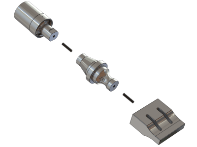
接头是超声叠堆中相邻部件之间的界面(接触区域)。接头的用途是高效地将超声能量传递通过接头,并为装配好的叠堆提供轴向和侧向刚度。典型的接头包括换能器—增幅杆接头和增幅杆—变幅杆接头。
|
|
|
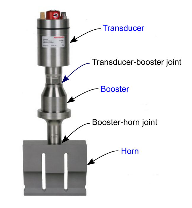
接头通常由螺纹螺柱紧固,便于装配和拆卸。不过有时也会采用其他紧固方式(如焊接或粘接剂)。超声接头(尤其是高振幅处的接头)的微动磨损是一个常见问题。这种微动磨损需要定期维护接头。
|
|
|
接头位置
对于纵向振动模态,谐振器按半波长增量设计,其每一端都是波腹。因此,波腹端是相邻谐振器之间(如变幅杆与增幅杆之间)的天然连接点。这些波腹接头处的超声(惯性)力很小,因此只需相对较小的静力即可将这些接头充分紧固。
但在某些情况下,接头位于偏离波腹的位置(例如端头的接头)。压电换能器中许多部件的接头都位于偏离波腹的位置。
设计
加工技术要求
下表列出了典型的加工技术要求。
|
|||||||||
|
接头所需的振幅均匀性
BUC——单槽、4.5" 宽、带凸耳的条形变幅杆。
接触面积
谐振器之间的接触通常发生在谐振器的标称尺寸处。例如,假设某个增幅杆的标称输出直径为 Ø40 mm,以达到所需的增益,那么它通常就在 Ø40 mm 直径处与变幅杆连接。然而,这未必是最优的。事实上,已有若干实例表明,减小接触直径可以改善性能。这种减小的接触直径是通过在增幅杆的输出面或变幅杆的输入面上加工一个短凸台来实现的。由于凸台高度很小(如 0.5 mm),相应谐振器的频率和增益基本不受影响。
复合变幅杆上的端头变幅杆
接头劣化(微动磨损)
超声接头可能因微动磨损而劣化。这会引起接头处的摩擦生热和微动碎屑(进而导致进一步劣化)。最终接头可能劣化到发出刺耳尖叫声的程度;这种不稳定会损坏换能器。在极端情况下,接头甚至会真正熔合在一起而无法拆卸。微动损伤是累积性的;微动磨损持续的时间越长,情况越糟。特别地,钛的抗微动磨损性能较差。(Youn[1])
如果两个配合的接头表面之间存在相对(摩擦)运动,就会产生微动磨损。这种相对运动只有在配合的接头表面受到驱动力作用时才会发生。如果接头位于纵向波腹处,理论上不应存在力。然而,这仅严格适用于接头直径较小且接头两侧材料相同的情况。如果这些条件不满足,接头处就可能存在振幅均匀性或径向振幅方面的不匹配。这种不匹配会诱发可能导致微动磨损的力。
(注 — 波腹处力(应力)为零这一条件,仅在变幅杆空载运行于空气中(无功率输出)时才严格成立。当向负载输送功率时,行波会沿叠堆传播并穿过接头。该行波伴有相应的应力,也可能促成微动磨损。目前尚不清楚这些应力是否足以引起微动磨损。)
那么位于偏离波腹位置的接头(例如端头的接头)又如何呢?尽管这些接头承受惯性力,但这些力的方向与谐振器轴线一致,而不是在接头表面平面内。因此,这类接头不一定会发生微动磨损。
微动磨损的概率随接头振幅的增大而增加。例如,在振幅较低的换能器—增幅杆接头处(如 20 kHz 下峰值 10 微米),微动磨损很少成为问题。然而,当使用 2.5:1 的增幅杆时,增幅杆—变幅杆接头处的微动磨损可能很显著。
钛
钛在自然状态下相对惰性。这是因为任何裸露的钛表面都会迅速形成一层氧化膜。然而,在没有这层氧化膜的情况下,裸露的钛具有很强的反应活性。因此,如果氧化膜被磨掉(如被微动磨损),暴露出的钛会倾向于与相邻金属发生反应。当相邻金属也是钛时尤其如此(例如钛增幅杆与钛变幅杆配合)。这种钛—钛微动磨损是骨科关节置换中的一个特殊问题,已被广泛研究。
不同直径
螺柱的影响
螺柱会使接头上的振幅分布发生畸变。畸变的程度取决于螺柱相对于谐振器的弹性模量。例如,考虑两个 Ø40 mm 谐振器之间的接头,一个由 Ti-6Al-4V 制成,另一个由 Al 7075-T6 制成。下表给出了这些谐振器的相对轴向振幅均匀性。
表面粗糙度
表面粗糙度可能显著影响微动磨损。Li 在对螺栓连接的不锈钢界面施加 25 Hz 切向载荷、循环 108 万次的试验中发现,将平均表面粗糙度(Ra)从 1 μm 增大到 4 μm ——
接头夹紧力分布
在典型的谐振器中,容纳螺柱的螺纹起始于靠近界面处(通常螺纹入口处有一个沉孔除外)。当两个这样的谐振器紧固在一起时,螺柱对接头施加的夹紧力集中在接头最靠近螺柱的部位。沿接头径向远离螺柱的方向,夹紧力逐渐减小,在接头边缘处降至最低。这种不均匀的夹紧力分布会导致微动磨损,尤其是在夹紧力较低的接头外周区域。
Stegelmann[1] 专利 6841921B2 声称,通过一种使螺柱仅在远离接头处与谐振器螺纹啮合的设计,可以改善夹紧力分布并减少微动磨损。其实现方式是:去掉螺柱中部的部分螺纹(使螺柱缩颈),或者对谐振器的螺纹进行锪孔,使这些螺纹去除到所需深度。这样,螺柱的力从谐振器内部更深处施加,而不是在接头附近施加,从而使接头上的力在整个接头上分布得更均匀。
|
|
|
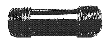
虽然 Stegelmann 专利背后的理论是成立的,但其新颖性(就专利而言)似乎值得怀疑。例如,这种方法早已被用于改善换能器中压电陶瓷上的静压力分布。(详见此处。)无论如何,对螺纹孔锪孔并非罕见做法,因此(以专利方式)限制这一做法在超声接头上的应用似乎并不合理。(Stegelmann 的专利于 2022 年 11 月到期。)
为了改善接头上的力分布,Culp[0] 在谐振器端面上加工了一个浅凹槽,只在谐振器端面外周附近留下一个接触环。例如,对于端面直径为 Ø40 mm 的谐振器(如增幅杆),在端面上加工一个 Ø30 mm × 深 0.5 mm 的凹槽,从而在外周留下一个 5 mm 宽的接触环。由于这个接触环相对较窄,环上的力分布相对均匀。这种方法对于承受横向载荷的接头特别有用,例如超声金属焊接中的接头。
输出功率
防护
人们尝试过各种界面材料以延长接头寿命。
垫片
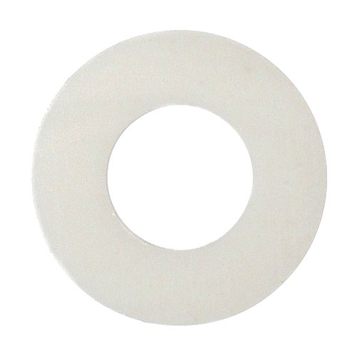
人们使用过薄的一次性垫圈。垫片材料包括铜和黄铜,厚度通常小于 0.2 mm。许多超声设备公司现在推荐使用聚酯(Mylar)垫圈。聚酯垫圈通常不与润滑剂一起使用。
Dukane[1](第 18 页)列举了聚酯垫圈相对于硅脂的以下优点 —
- 在大多数情况下,垫圈在生产中的使用寿命更长。
- 界面微动磨损(劣化)减少。
- 由于垫圈厚度一致,叠堆装配更加一致。
- 叠堆拆卸通常需要更小的扭矩,并降低损坏部件的可能性。
然而,Dukane[1](第 13 页)也指出,聚酯垫圈在压力下会发生蠕变,因此维护计划应包括定期检查和更换。
|
|
|
润滑剂
有几家公司将聚酯垫圈作为首选。不过,他们可能推荐硅脂作为(通常效果较差的)替代方案。
- Dukane[1](第 13 页)推荐薄涂一层 Dow-Corning #4 高温高压硅脂(或以 #111 作为替代)。
- Branson[4](第 2 页)对 40 kHz 叠堆推荐 Dow-Corning #111 —— "通常,40 kHz 产生的振幅不足以引起微动腐蚀。" 然而,对于 15 kHz 至 30 kHz 的叠堆,Branson 表示使用聚酯垫圈(代替硅脂)可以将微动腐蚀降至最低。
高压防卡死润滑脂已被有效使用。其中,钼基润滑脂(如 Dow Corning 的 Molykote M-77(dowcorning.com),适用温度可达 400°C)颇受欢迎。其他润滑脂可能同样有效。
有一家公司使用薄层透明特氟龙(Teflon)喷剂。据报道效果良好。 Culp[0]
然而,对于其带解耦盘的 20 kHz 缝焊机(很可能为钛制),Stapla Ultrasonics[1] 建议:"耦合表面必须无油脂、无油污。"(第 14 页)
注 —
- 在要求生物相容性的场合,许多润滑剂可能不适用。
- 旋塞脂曾一度被广泛使用。然而,旋塞脂是为密封实验室化学设备的真空泄漏而设计的。其润滑性能较差,且长期使用后会留下坚硬的残留物。
镀层
镀铬、阳极氧化
其他
如果上述建议仍不够,可以尝试以下方法。
- 增大变幅杆增益。在相同输出振幅下,这会降低增幅杆—变幅杆接头处的振幅。
- 取消接头。将变幅杆和增幅杆用一整块材料制成(即全波长变幅杆),从而消除这个麻烦的接头。如果变幅杆是矩形的,这可能不太现实,尤其是当变幅杆很大时,为获得增幅杆形状需要去除大量毛坯材料。
- 熔合接头。接头可以通过电子束或激光束焊接实现熔合。这可能需要在变幅杆上设置一个凸起的焊台,以便让焊束能够接近接头。根据变幅杆和增幅杆的材料,旋压焊接和钎焊也可能可行。不过,旋压焊接通常只用于大批量应用。熔合接头也可以通过热等静压(HIP)成形 — 例如参见 Ehlert[1] 专利 8,459,122 B2。
紧固
工具
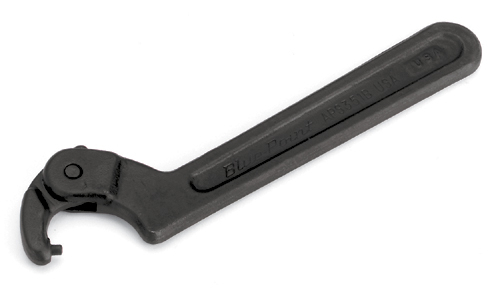
为了将两个谐振器紧固在一起,配合的谐振器必须加工出适合相应扳手的结构。扳手结构通常是扳手平面(适用于开口扳手)或径向孔(适用于销式扳手)。销式扳手很常见,但有以下局限 —
- 持续使用会使谐振器的销孔磨损滑牙,铝制谐振器尤其如此。
- 只适用于圆柱形谐振器。
- 不适用于小直径谐振器。
- 可施加的扭矩有限,原因要么是销式扳手的销钉会折断,要么是销钉会从销孔中滑脱。
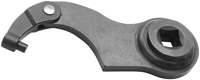
- 如果要与扭矩扳手配合使用,则需要一种特殊且不常见的转接头(图 2b)。(相比之下,扳手平面只需要爪形(clawfoot)扳手转接头,后者要常见得多。)
在空间不足以容纳普通扳手,或普通扳手尺寸大到无法接受的情况下,销式扳手会更有优势。
|
||||||||||
|
|
|
|
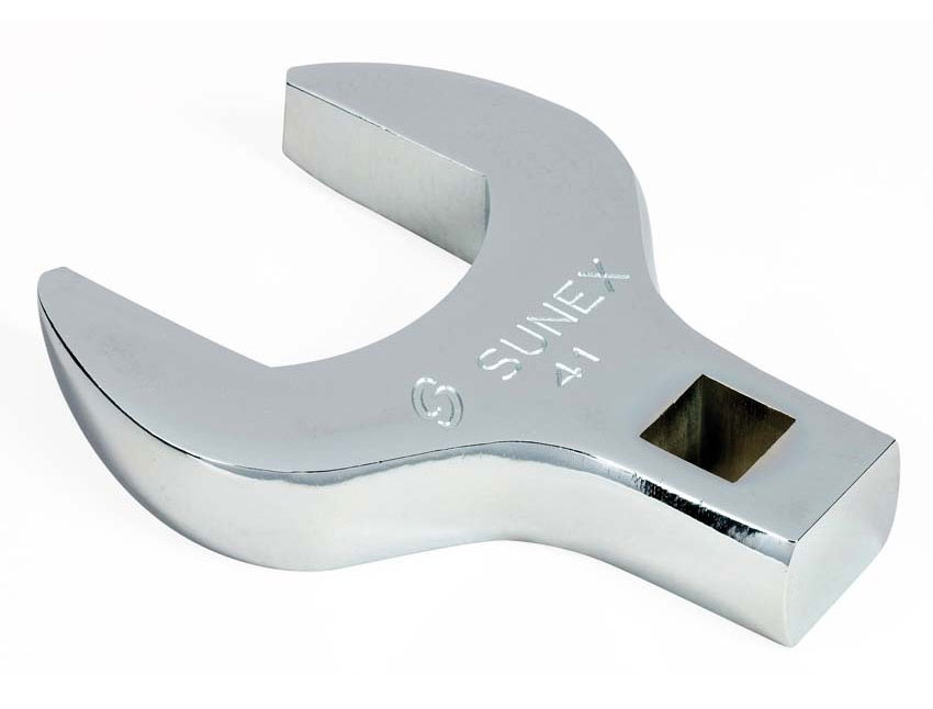
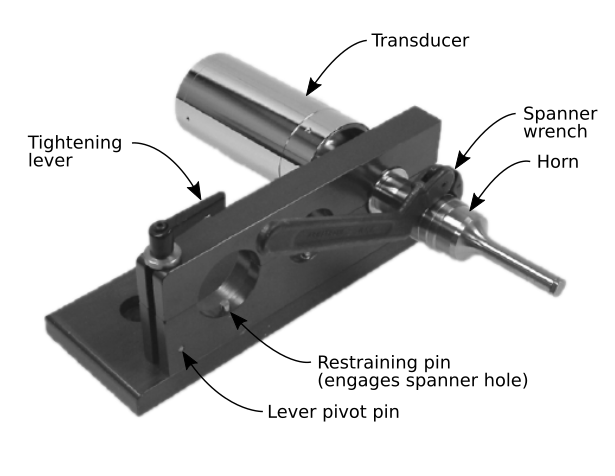
图 4 展示了一种常见的蛤壳式夹具,用于带径向销孔的谐振器。在该图示中,夹具卡住换能器的销孔,而销式扳手卡住变幅杆的销孔。(注意在此例中,销式扳手的啮合方向是用于松开变幅杆。)这种夹具还有两个额外的孔,以适应不同直径的谐振器。这种设计可以有简单的变体(例如,用带适当钳口适配器的台虎钳代替蛤壳式夹具)。
|
|
|
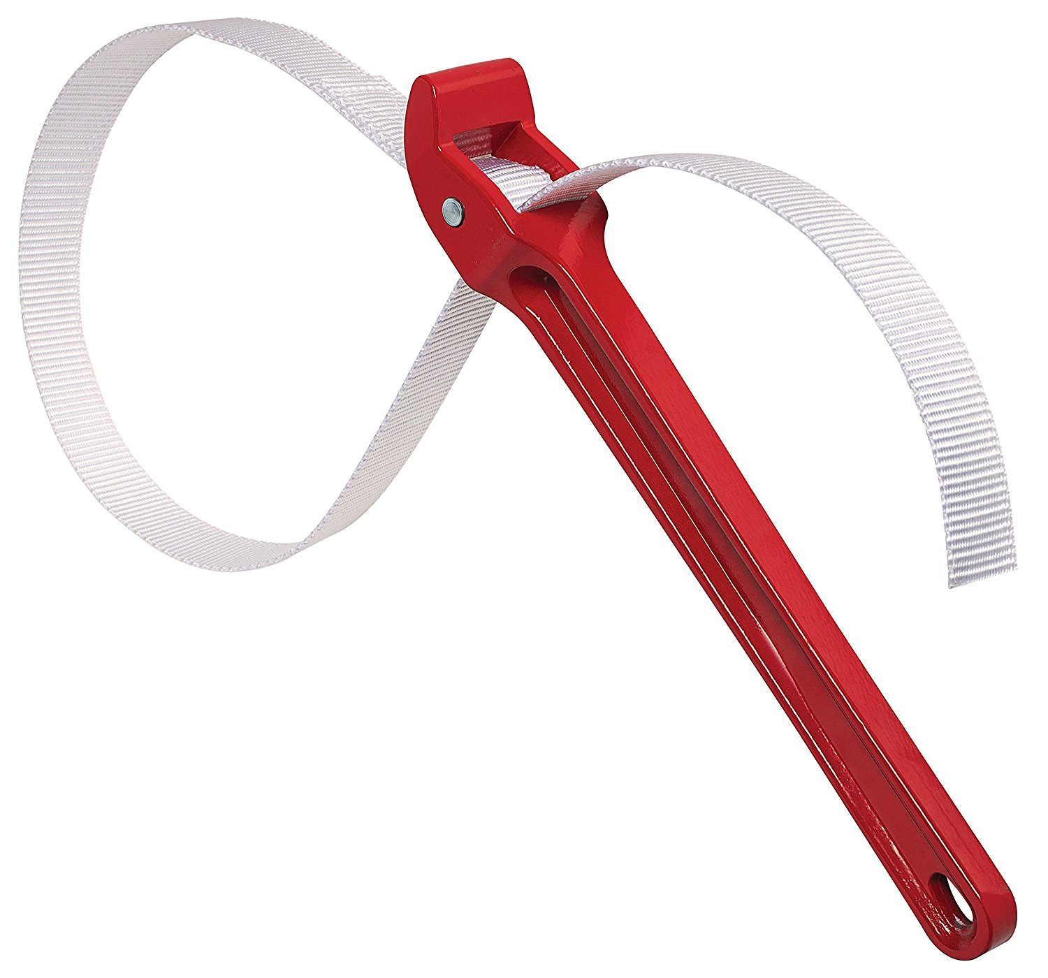
如果谐振器没有可施加扳手的结构(例如条形变幅杆、块形变幅杆或大型圆柱形变幅杆),则可以使用织物或橡胶带式扳手。或者,也可以用带软钳口(如铝或铜)的台虎钳将其夹紧,以免划伤谐振器表面。否则,这种划伤可能成为疲劳裂纹的起始位置。
|
|
|
注意事项
紧固接头时,不应通过增幅杆的安装环来固定增幅杆,也不应通过换能器的外壳来固定换能器。这些部位通常带有防转销,而防转销并非为承受高扭矩而设计。
扭矩
为使配合的接头表面保持紧密接触,需要一定的静态接头力。由于所施加的静力不易测量,因此用接头扭矩作为替代指标。然而,给定扭矩所产生的力取决于多种因素,如接头和螺纹的摩擦系数(取决于润滑剂、表面粗糙度、材料)、加工质量(接头表面粗糙度、垂直度)、螺纹螺距、接触面积等。(参见 Nutek[1],第 B–4 页)例如,以下情况在相同扭矩下会产生不同的接头力 —
- 不同的摩擦系数
- 无润滑与有润滑
- 配合的谐振器材料 — 钛—钛、钛—铝、铝—铝
- 界面垫片 — 铜与聚酯(Mylar)
- 螺柱材料 — 钢与钛
- 不同的螺纹螺距 — 3/8-24 螺纹与 1/2-20 螺纹
- 不同的接触直径 — 25 mm 与 40 mm
对于具有标称参数的接头(假设设计良好),Nutek[1](第 B–43 页)指出,规定扭矩所产生的接头力精度仅在 ±35% 以内。Unbrako(第 62 页)估计为 ±25%。
因此,由给定扭矩产生的接头力是非常近似的。所以,各扭矩推荐值之间的比较难以评估。
无显著横向载荷的变幅杆
在大多数超声应用中,变幅杆输出面上要么不施加静载荷(如液体处理),要么静载荷主要平行于叠堆轴线(如塑料焊接)。此时接头主要承受压缩载荷。(注 — 如果塑料焊接变幅杆较宽,且其端面上的接触不均匀,则接头还将承受一些必须予以抵抗的静态弯矩。)
|
|||||||||||||||||||||||||||
|
表注 —
- 参考文献 —
- Branson Ultrasonics[3](第 2 页)
- Dukane[1](第 14 页)
- Patsonics[1]
- Sonics & Materials[2](第 12 页)— 告诫不要拧得过紧
表 1 显示,Dukane 推荐的紧固扭矩明显高于 Branson。Dukane 指出:"变幅杆和增幅杆的扭矩规格高于螺柱扭矩规格。请务必将变幅杆或增幅杆接头紧固到更高的扭矩限值。"(第 14 页)另一方面,Branson 的接头扭矩通常小于其螺柱扭矩,表面上的原因是为了防止在紧固接头时,已触底的螺柱从螺柱孔底部松脱。(Culp[0])然而,Branson 金属焊机的接头扭矩(108 Nm,见下文)是其 ½‑20 螺柱 51 Nm 推荐扭矩的 2 倍;尽管如此,这些接头的故障率相对较低。另外,在一个案例中,一位 Branson 客户以约为 Branson 推荐扭矩 3 倍的扭矩将变幅杆紧固到钛增幅杆上,并报告效果良好。(Culp[0]) 不过,这位客户可能同时也更换了接头润滑剂。 因此,接头扭矩的巨大差异表明,人们对扭矩对接头性能和接头寿命的影响还缺乏充分的认识。
Cardoni[1](第 179 页)指出:"大功率超声领域一直公认,系统部件的仔细装配对获得良好的系统性能至关重要。关于螺柱尺寸、螺柱位置以及部件连接的扭矩要求,已有许多"经验法则"被采用,尽管各制造商的建议之间存在不一致。"
有显著横向载荷的变幅杆
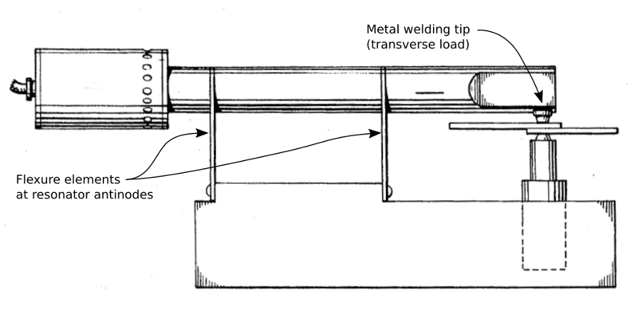
在剪切焊接应用(金属焊接、管材封合)中,变幅杆的输出面位于变幅杆侧面而非端面(图 6)。当静(横向)载荷施加到该输出面时,接头承受的弯矩倾向于使接头张开。因此,接头必须比正常情况拧得更紧。
|
|
|
|
||||||||||||||||||||||||
|
表注 —
- 该扭矩值同时适用于换能器—增幅杆接头和增幅杆—变幅杆接头。(Stapla Ultrasonics[2],第 12、49 页)
- 该缝焊机使用解耦盘。(Stapla Ultrasonics[1],第 14 页)"耦合表面必须无油脂、无油污。" 缺少润滑意味着接头处产生的轴向力将低于其他情况下的预期值。
- 极性安装座(Culp[0])
非线性行为
图 7 给出了 Cardoni[1] 的数据,其表明"更紧"的接头可减少非线性行为。然而,文中未给出试验细节,因此这一结论难以推广。(对于理想接头,图 7a 和图 7b 中的虚线应完全垂直,且拟合数据点的曲线应关于每条虚线左右对称。)
|
||||||||||
|
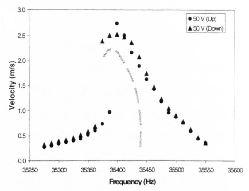
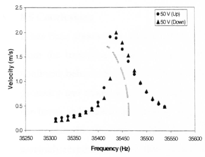
Mathieson[1](第 146-151 页)提供了一些补充信息。然而,Mathieson 没有给出具体的扭矩值,只是将他的接头分类为"松"和"紧"。可以推测存在一个极限扭矩(接头应力),超过该值后超声性能不再有实质性改善。(这与 Hulst 的图 5b 中压电陶瓷预应力数据类似。)然而,根据 Mathieson 有限的数据无法确定这一极限。
部分基于相关研究,Mathieson[1](第 151 页)得出结论:"经过调谐的超声组件中两个部件之间的连接,会对性能以及设备是否表现出强烈的非线性行为产生很大影响。实现稳定可靠的超声接头的重要因素是:支承面之间的高精度,以及在两个连接部件之间施加尽可能高的允许扭矩。"
端头
标准端头请参见此处。
连接
电子束焊接、钎焊
维护
接头会随时间劣化。特定叠堆配置的确切劣化速率不易估算;必须通过经验来确定。Dukane[1](第 15 页)建议在最初运行 200-400 小时后检查叠堆接头。如果接头状况可接受,则将检查间隔加倍。然而,如果接头需要修复,则将检查间隔减半。
修复
如果界面已劣化,通常可以通过去除少量材料来修复。
手工修复
如果劣化轻微,可以用手工修复表面。以下流程由 Branson(第 3 页)、Dukane(第 25 页)、Patsonics[1] 和 Sonics and Materials[2](第 20 页)推荐(略有差异)。
- (按需)拆下螺柱并将表面擦拭干净。
- 将一张干净的 #400 粒度(或更细)砂布砂面朝上粘贴到干净、平整的表面上,如一块平板玻璃。
- 在谐振器底部附近用拇指和食指或中指捏住谐振器。这种握持位置可减少谐振器晃动(晃动会产生凸面)或打颤的倾向。
- 在施加最小向下压力的同时,沿一个方向轻轻地推动或拉动谐振器通过砂布。(注 — Sonics & Materials 推荐采用 8 字形轨迹。然而,Patsonics 明确指出应沿直线拉动谐振器,"不要走 8 字形或其他轨迹。")重复一次。
- 将谐振器旋转 120° 并重复步骤 4。再重复一次。
- 重复步骤 4 和 5,直到所有点蚀和污染物都被去除。
- 将一把直尺(如金属直尺的边)横放在修复后的表面上,并对着光线观察。如果在修复表面的外周能看到光线,则该表面为凸面。这种表面只能通过机械加工修复。
- 按规格安装螺柱。(如果原来的螺柱未触底,则可以重复使用。但是,如果曾涂过螺纹锁固剂,则应先清除该材料。可以将螺柱轻轻地通过板牙,或用钢丝刷清除。如果原来的螺柱曾触底,则应更换,因为螺柱端部很可能在首次安装时已受损。)
机械加工修复
Joints
Contents
- Figures
- Figure 0. Joints for industrial ultrasonic stack
- Figure 0a. Industrial ultrasonic stack assembly
- Figure 0b. Necked stud
- Figure 1. Mylar washer
- Figure 2. Spanner wrenches
- Figure 3. Crowfoot (clawfoot) wrench adapter
- Figure 4. Clamshell tightening fixture (Branson Ultrasonics)
- Figure 5. Strap wrench
- Figure 6. Metal welding stack supported by flexure elements
- Figure 7. Effect of joint tightness on nonlinear response
A joint is an interface (area of contact) between adjacent components of an ultrasonic stack. The purpose of the joint is to efficiently transfer ultrasonic energy across the joint and to provide axial and lateral stiffness to the assembled stack. Typical joints include the transducer-booster joint and the booster-horn joint.
|
|
|
Joints are typically secured by threaded studs which permit easy assembly and disassembly. However, other means of securing (e.g., welding or adhesives) are sometimes used. Fretting at ultrasonic joints (especially those at high amplitude) is a common problem. Such fretting requires periodic joint maintenance.
|
|
|
Joint locations
For axial mode vibration, resonators are designed to vibrate in half-wave increments where each end is an antinode. Hence, the antinode ends are natural attachment points between adjacent resonators (e.g., between the horn and booster). The ultrasonic (inertial) forces at these antinode joints are low so relatively little static force should be needed to adequately secure these joints.
In some cases, however, joints are located away from antinodes (e.g., for tips). Joints for many of the components in a piezoelectric transducer are located away from the antinode.
Design
Machining specifications
The following table shows typical machining specifications.
|
|||||||||
|
Required joint amplitude uniformity
BUC - 1-slot 4.5" wide bar horn with ears.
Contact area
Contact between resonators usually occurs at the resonator's nominal dimensions. For example, suppose a booster's nominal output diameter is Ø40 mm in order to achieve the desired gain. Then it would normally be joined to the horn at the Ø40 mm diameter. However, this might not be optimal. In fact, there are several instances where a reduced contact diameter has shown improved performance. This reduced contact diameter is achieved by machining a short boss on either the output surface of the booster or the input surface of the horn. Since the boss height is small (e.g., 0.5 mm), the frequency and gain of the associated resonator are relatively unaffected.
Tip horns on composite horns
Joint deterioration (fretting)
Ultrasonic joints may deteriorate due to fretting. This causes frictional heating at the joint and fretting debris (which then leads to further deterioration). Eventually the joint may deteriorate to the extent that it causes squealing; such instability can damage the transducer. In extreme cases the joint may literally become fused so that it can't be disassembled. Fretting damage is cumulative; the longer fretting continues the worse the condition becomes. In particular, titanium has poor fretting resistance. (Youn[1])
Fretting will result if there is relative (frictional) motion between the two mating joint surfaces. Such relative motion can only occur if the mating joint surfaces are subjected to driving forces. If the joint is located at a longitudinal antinode then, in theory, no force should be present. However, this strictly applies only where the joint diameters are small and where the material on each side of the joint is the same. If these conditions are not true then there may be incompatibilities in amplitude uniformity or radial amplitudes at the joint. Such incompatibilities induce the forces that may lead to fretting.
(Note — The condition of zero force (stress) at an antinode is strictly true only when a horn is running in air (no power delivery). When power is delivered to a load, a traveling wave passes along the stack and through the joint. This traveling wave has associated stresses which may also contribute to fretting. It is not known if these stresses are sufficient to cause fretting.)
What about joints that are located away from an antinode (e.g., for tips)? Although these joints experience inertial forces, these forces are aligned with the resonator axis, rather than in-plane with the joint surface. Hence, such joints will not necessarily experience fretting.
The probability of fretting increases with the joint amplitude. For example, fretting is rarely a problem at the transducer-booster joint which has low amplitude (e.g., 10 microns peak at 20 kHz). However, fretting can be significant at the booster-horn joint when a 2.5:1 booster is used.
Titanium
In its natural state titanium is relatively inert. This is due to an oxide film that quickly forms over any raw titanium. However, raw titanium is very reactive in the absence of this oxide film. Thus, if the oxide film is abraided (e.g., by fretting) then the exposed titanium will tend to react with an adjoining metal. This is particularly true if the adjoining metal is also titanium (e.g., a titanium booster mated to a titanium horn). This titanium-titanium fretting is a particular problem for orthopaedic joint replacements and has been studied extensively.
Different diameters
Effect of stud
A stud distorts the amplitude across a joint. The distortion depends on the modulus of the stud relative to the resonator. For example, consider a joint between two Ø40 mm resontors, one made of Ti-6Al-4V and one of Al 7075-T6. The following table shows the relative axial amplitude uniformities of these resonators.
Surface finish
Surface finish may significantly affect fretting. In tangential loading of a bolted stainless steel interface at 25 Hz for 1.08 million cycles, Li found that increasing the average surface finish (Ra) from 1 μm to 4 μm ---
Joint clamp force distribution
In a typical resonator the thread that accommodates the stud starts close to the interface surface (except typically for a countersink at the thread's entrance). Then when two such resonators are tightened together the clamp force of the stud on the joint is concentrated a the joint nearest to the stud. Moving radially on the joint away from the stud, the clamp force decreases, declining to a minimum at the edge of the joint. This nonuniform clamp force distribution can lead to fretting, especially toward the joint periphery where the clamp force is low.
Stegelmann[1] patent 6841921B2 claims that the clamp force distribution can be improved and fretting can be reduced by a design whereby the stud only engages the resonator's threads away from the joint. This is accomplished either by removing a central portion of the stud threads (necking the stud) or by counterboring the resonator's threads so that these threads are removed to the desired depth. Then the force of the stud is exerted from deeper within the resonator rather than near the joint so that the force on the joint is more evenly distributed across the joint.
|
|
|
While the theory behind Stegelmann's patent is valid, the novelty (for patent purposes) seems doubtful. For example, this method has been used to improve the static pressure distribution across the piezoelectric ceramics in a transducer. (See details.) In any case, counterboring of tapped holes is not uncommon so restricting this practice (by patent) at an ultrasonic joint would seem unreasonable. (Stegelmann's patent expires in November 2022.)
To improve the force distribution across the joint, Culp[0] machined a shallow recess in the resonator's face, leaving only a contact ring near the periphery of the resonator's face. For example, for a resonator (e.g., booster) with a Ø40 mm face diameter, a Ø30 mm x 0.5 mm deep recess was machined into the face, thereby leaving a 5 mm wide contact ring around the periphery. Because this contact ring is relatively narrow, the force distribution across the ring is relatively uniform. This method is particularly useful for joints that are subject to transverse loads, such as in ultrasonic metal welding.
Delivered power
Protection
Various interface materials have been tried in order to extend joint life.
Shims
Thin disposable shim washers have been used. Shim materials include copper and brass, typically less than 0.2 mm thick. A number of ultrasonic companies now recommend mylar washers. Mylar washers are normally used without lubricants.
Dukane[1] (p. 18) cites the following benefits of mylar washers compared to silicone grease —
- In most cases the washer will last longer in production.
- Interface fretting (deterioration) is reduced.
- Stack assembly is more consistent since the washers have consistent thickness.
- Stack disassembly will often require less torque and reduce the possibility of damaging components.
However, Dukane[1] (p. 13) also notes that mylar washers will creep under pressure so a maintenance plan should include periodic inspection and replacement.
|
|
|
Lubricants
Several companies recommend mylar washers as a first choice. However, they may recommend silicone grease as a (generally less effective) alternative.
- Dukane[1] (p. 13) recommends a thin layer of Dow-Corning #4 high temperature, high pressure silicone grease (or #111 as an alternative).
- Branson[4] (p. 2) recommends Dow-Corning #111 for 40 kHz stacks — "Typically, 40 kHz does not generate enough amplitude to create fretting corrosion." However, for 15 kHz to 30 kHz stacks Branson says that using mylar washers (instead of silicone grease) will minimize fretting corrosion.
High pressure anti-seize greases have been used effectively. Of these, molybdenum based greases (such as Dow Corning's Molykote M-77 (dowcorning.com), suitable up to 400°C) are popular. Others may be equally effective.
One company uses a thin layer of transparent Teflon spray. The results are reportedly good. Culp[0]
However, for their 20 kHz seam welder with decoupling disks (probably titanium), Stapla Ultrasonics[1] recommends, "The coupling surfaces must be free of grease and oil." (p. 14)
Notes —
- Many lubricants may not be suitable where biocompatibility is required.
- At one time stopcock grease was widely used. However, stopcock grease is designed to seal against vacuum leaks in laboratory chemical equipment. Its lubricating properties are poor and it leaves a hard residue after longterm use.
Platings
Chrome, anodize
Other
If the above suggestions are not adequate then the following can be tried.
- Increase the horn gain. For the same output amplitude, this will reduce the amplitude at the booster-horn joint.
- Eliminate the joint. Make the horn and booster from a single piece of material (i.e., a full-wave horn), thereby eliminating the troublesome joint. This may be somewhat unrealistic if the horn is rectangular, especially if the horn is large so that significant raw stock removal would be required in order to achieve the booster shape.
- Fuse the joint. The joint can be fused by electron beam or laser beam welding. These might require a raised pad on the horn in order to allow the beam to access to the joint. Spin welding and brazing might be possible, depending on the horn and booster materials. However, spin welding is typically reserved for high volume applications. The fused joint might be formed by hot isostatic pressing (HIP) — e.g., see Ehlert[1] patent 8,459,122 B2.
Tightening
Tools
In order to tighten two resonators together, the mating resonators must be machined to accept the appropriate wrenches. The wrenching geometry is typically either wrench flats (to accept open-end wrenches) or radial holes (to accept spaner wrenches). Spanner wrenches are common but have the following limitations —
- They can strip out the resonator's spanner holes with continual use, particularly with aluminum resonators.
- They are only suitable for cylindrical resonators.
- They are not available for small diameter resonators.
- The torque that can be applied is limited, either because the spanner's pin will break or the pin will slip from the spanner hole.
- If they are to be used with a torque wrench then they need a special, uncommon adapter (figure 2b). (In contrast, wrench flats only require a crowfoot wrench adapter (also called a clawfoot wrench adapter) which is much more widely available.)
Spanner wrenches can be advantageous where there is limited room for a conventional wrench or when a conventional wrench would be unacceptably large.
|
||||||||||
|
|
|
|
Figure 4 shows a common type of clamshell fixture for resonators with radial spanner holes. In this illustration the fixture engages the spanner holes of the transducer while a spanner wrench engages the spanner holes of the horn. (Note in this case that the spanner wrench is engaged so as to loosen the horn.) This particular fixture has two additional holes to accommodate resonators of different diameters. Simple variations of this design are possible (e.g., by substituting a bench vise with appropriate jaw adaptors for the clamshell).
|
|
|
If a resonator does not have a means for applying a wrench (e.g., a bar horn, block horn, or large cylindrical horn) then a fabric or rubber strap wrench may be used. Alternately, it may be clamped in a vise with soft jaws (e.g., aluminum or copper) so that the resonator's surface will not be marred. Otherwise, such marring could be a location for fatigue crack initiation.
|
|
|
Caution
When tightening a joint, the booster should not be held by its mounting rings and the transducer should not be held by its housing. These typically have anti-rotation pins that are not designed to withstand high torque.
Torques
A certain static joint force is needed to maintain intimate contact between mating joint surfaces. Since the applied static force can't be easily measured, joint torque is used as a proxy. However, the force exerted by a given torque will depend on factors such coefficients of friction for the joint and threads (depending on lubricants, finishes, materials), machining (joint finish, perpendicularities), thread pitch, contact area, etc. (See Nutek[1], p. B–4) For example, the following will give different joint forces for identical torques —
- Different coefficients of friction
- Unlubricated versus lubricated
- Mated resonator materials — titanium-titanium, titanium-aluminum, aluminum-aluminum
- Interface shims — copper versus mylar
- Stud material — steel versus titanium
- Different thread pitches — 3/8-24 thread versus 1/2-20 thread
- Different contact diameters — 25 mm versus 40 mm
For joints with nominal parameters (assuming well designed), Nutek[1] (p. B–43) indicates that a specified torque will produce a joint force that is only accurate within ±35%. Unbrako (p. 62) estimates this as ±25%.
Thus, the joint force from a given torque is very approximate. Hence, comparisons among torque recommendations are difficult to evaluate.
Horns without substantial transverse loads
In most ultrasonic applications there is either no static load applied to the horn's output face (e.g., liquid processing) or the static load is mainly parallel to the stack axis (e.g., plastic welding). Then the joints are loaded mainlly in compression. (Note — If a plastic welding horn is wide and if contact is not uniform across its face then the joints will also experience some static bending moments which must be resisted.)
|
|||||||||||||||||||||||||||
|
Table notes —
- References —
- Branson Ultrasonics[3] (p. 2)
- Dukane[1] (p. 14)
- Patsonics[1]
- Sonics & Materials[2] (p. 12) — cautions not to overtighten
Table 1 shows that Dukane recommends significantly higher tightening torques than Branson. Dukane notes that, "Horn and booster torque specifications are higher than stud torque specs. Be sure to tighten the horn or booster joints to the higher torque limits." (p. 14) On the other hand, Branson's joint torques are generally less than its stud torques, ostensibly to keep the bottomed stud from loosening from the bottom of the stud hole as the joint is tightened. (Culp[0]) However, the joint torque of Branson's metal welder (108 Nm, below) is 2x greater than its 51 Nm recommended torque for the ½‑20 stud; none-the-less, these joints are relatively trouble free. Also, in one case a Branson customer tightened the horn to a titanium booster at approximately 3x Branson's recommended torque and reported good results. (Culp[0]) However, this customer may also have changed joint lubricants at the same time. Thus, the wide variation in joint torques shows that the effects of joint torque on performance and joint longevity are not well understood.
Cardoni[1] (p. 179) notes, "It has always been understood in the high power ultrasonics community that careful assembly of system components is critical for good system performance. There have been many "rules of thumb" applied, concerning stud sizes, stud position and torque requirements for joining components, although there are inconsistencies between manufacturers recommendations."
Horns with substantial transverse loads
In shear welding applications (metal welding, tube sealing) the horn's output surface is on the side of the horn rather than on the face (figure 6). When the static (transverse) load is applied to this output surface, the joints experience bending moments that tend to cause the joints to open. Hence, the joints must be tightened tighter than normal.
|
|
|
|
||||||||||||||||||||||||
|
Table notes —
- The torque value is for both the transducer-booster and booster-horn joints. (Stapla Ultrasonics[2], pp. 12, 49)
- The seam welder uses decoupling disks. (Stapla Ultrasonics[1], p. 14) "The coupling surfaces must be free of grease and oil." The lack of lubrication means that the resulting axial force at the joint will be less than othewise expected.
- Polar mount (Culp[0])
Nonlinear behavior
Figure 7 shows data from Cardoni[1] who indicates that a "tighter" joint reduces nonlinear behavior. However, no details of the test are given so generalization of this conclusion is difficult. (For an ideal joint, the broken lines of figures 7a and 7b would be completely vertical and a curve fitted to the data points would be symmetric left-to-right about each line.)
|
||||||||||
|
Mathieson[1] (pp. 146-151) provides some additional information. However, Mathieson does not provide specific torque values but only classifies his joints as "loose" and "tight". Presumably there is a limiting torque (joint stress) beyond which the ultrasonic performance doesn't substantially improve further. (This would be similar to the piezoceramic prestress data of Hulst, figure 5b.) However, this limit can't be determined from Mathieson's limited data.
Based, in part, on related studies, Mathieson[1] (p. 151) concludes, "The join between two component of a tuned ultrasonic assembly can have a large effect on the performance and whether strong nonlinear behaviours are exhibited by the device. Important factors in achieving a stable and reliable ultrasonic joint are high accuracy between the bearing surfaces combined with as high a torque as allowable between the two joining parts."
Tips
See here for standard tips.
Joining
EB welding, brazing
Maintenance
Joints may deteriorate over time. The exact deterioration rate for a particular stack configuration can't be easily estimated; it must be established through experience. Dukane[1] (p. 15) recommends inspecting the stack joints after the first 200-400 hours of operation. If the joints are acceptable then double the inspection interval. However, if the joints require reconditioning then halve the inspection interval.
Reconditioning
If an interface surface has deteriorated then it can often be reconditioned by removing a small amount of material.
Manual reconditioning
If the deterioration is slight then the surface can be reconditioned by hand. The following process is recommended (with slight variations) by Branson (p. 3), Dukane (p. 25), Patsonics[1], and Sonics and Materials[2] (p. 20).
- Removed the stud (as needed) and wipe the surface clean.
- Tape a clean sheet of #400 grit (or finer) emery cloth grit side up to a clean, flat surface such as a piece of plate glass.
- Hold the resonator between the thumb and index or middle finger near the bottom of the resonator. This position will reduce the tendency of the resonator to rock (which would produce a convex surface) or shudder.
- While applying minimal downward force, push or pull the resonator gently across the emery cloth in one direction. (Note — Sonics & Materials recommends a figure 8 pattern. However, Patsonics specifically states that the resonator should be pulled in a straight line, "not in a figure 8 or other pattern.") Repeat once.
- Rotate the resonator 120° and repeat step 4. Repeat.
- Repeat steps 4 and 5 until all pitting and contamination have been removed.
- Place a straight edge, such as the edge of a metal ruler, across the repaired surface and hold this up to the light. If any light can be seen at the periphery of the repaired surface then the surface is convex. This surface can only be repaired by machining.
- Install a stud to specification. (If the original stud was unbottomed then it can be re-used. However, if a threadlocking material had been applied then that material should first be removed. This can be done by running the stud lightly through a die or by using a wire brush. If the original stud had been bottomed then it should be replaced since the point would likely have been damaged from the first installation.)