隔振安装座
目录
- 插图
概述
在大多数应用中,必须提供某种方式将超声叠堆安装到支撑结构上。(超声清洗是一个例外,此时换能器直接连接到清洗槽壁上。)根据应用的不同,隔振安装座可以连接到换能器、增幅杆(最常见)和/或变幅杆上。支撑结构可以是某种支架(例如用于塑料焊接),也可以是外壳(例如用于手持设备)。
要求
- 安装座必须对超声叠堆进行声学隔离。否则,超声能量将传递到支撑结构上。
—— 这部分能量被浪费了(无法施加到负载上)。
—— 这部分能量会产生摩擦,可能导致支撑结构咬粘、发热(例如外壳为手持式时)或产生噪声。 - 安装座必须能够使叠堆的输出表面相对于负载进行合理的精确定位。
- 安装座必须防止在所施加载荷下出现过大的轴向或横向挠曲。
类型
安装座一般有两种类型 —— 弹性体安装座和刚性安装座。弹性体安装座利用弹性体(例如橡胶)实现隔振,最常见的弹性体形状是 O 形圈。刚性安装座采用全金属结构,用于需要高刚度(静载荷下低挠曲)和精确定位的场合。不过,刚性安装座比弹性体安装座更昂贵,且容差性较差。
O 形圈安装座
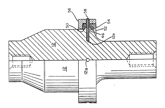
除了对超声叠堆进行声学隔离外,O 形圈还能在冲击载荷下提供缓冲。通常,在 O 形圈法兰的每一侧各安装一个 O 形圈(图 1)。只要 O 形圈法兰和外壳的公差合适,当换能器本体装配到外壳中时,O 形圈就会被轻微压缩。
(在本讨论中,"外壳"定义为包夹 O 形圈的元件。因此,举例来说,外壳可以是围绕增幅杆 O 形圈法兰的环,也可以是包覆换能器本体的组件。使用时,外壳通常以某种方式夹紧到支撑结构上。)
|
|
|
|
||||||||||||||||
|
图 1 注释 ——
- 内壳环(54)被压入外壳环(56)中。这将 O 形圈压紧在 O 形圈法兰(46)上。然后安装防转销(58)。
- 一旦装配完成,只有通过破坏销(例如钻孔或电火花加工)才能拆开外壳。因此,更换 O 形圈是不现实的。
|
|
|
|
||||||||||||||||||
|
图 2 注释 ——
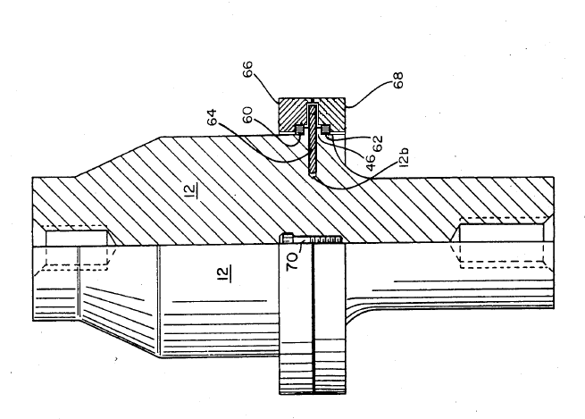
- 后壳环(66)用螺钉(70)固定到前壳环(68)上,通常为 6 个。这将 O 形圈压紧在 O 形圈法兰(46)上。
- 壳环上供防转销(58)嵌入的让位槽可以在装配前用球头立铣刀加工在环上。此时必须在装配前安装防转销。或者,也可以在装配后钻通让位槽,然后再安装防转销。
- 这种设计便于更换 O 形圈,但加工和装配成本高于图 1 的设计。
可以有多种变型。例如,图 1 中的内环可以采用滑配合而非压配合。然后可以用卡环固定,卡环嵌入外环的内槽中。槽式 zzz。
O 形圈规格
如果 O 形圈在应用中(例如塑料焊接)会受到压缩或冲击,则必须选择具有适当抗拉强度的材料。例如,作为一类材料,聚氨酯弹性体具有较高的抗拉强度,而硅橡胶弹性体的抗拉强度相对较低(Parker (2),第 2‑6 页)。Coenen 专利 4,647,336建议使用硬度为 90 邵氏硬度的 Viton 氟橡胶 O 形圈(第 5 页,第 5 行)。(注 —— 在许多应用中(例如塑料焊接),当压力施加到变幅杆端面上时,只有后 O 形圈受到压缩。此时,如有需要,前 O 形圈可以采用明显更低的硬度。)
选定材料后,必须确定 O 形圈的尺寸,使其能够反复承受载荷;一般来说,载荷越大,需要的 O 形圈越粗。例如,图 1 和图 2 中的换能器使用 3.5 mm 粗的 O 形圈。如果有第二个谐振器(例如增幅杆)与换能器分担载荷,则换能器的 O 形圈可以更细。
O 形圈尺寸确定后,可以调整前驱动块和外壳中 O 形圈座面的尺寸,以获得所需的配合。一般来说,这些尺寸可以与静态流体密封应用的尺寸相同(Parker (2),第 4 节),但必须满足所需的 O 形圈静态压缩量(见下文)。当然,也可以将 O 形圈拉伸后装配,但拉伸量应限制在 5% 以内,因为由此产生的内应力会加速老化(Parker (2),第 3‑9 页)。
注 —— 曾试用过方形"O 形圈"。这些试验表明,方形"O 形圈"在隔离外壳与换能器本体方面效果较差。这些试验的细节不详。
静态压缩
装配后,O 形圈必须受到足够的压缩,以使外壳不会绕前驱动块"晃动"。但是,如果 O 形圈压缩过度,它们会将超声能量传递到外壳上。压缩量取决于 O 形圈的硬度。此外,还应考虑压缩永久变形、温度效应、老化等因素。(参见 Parker (2)。)
Coenen 专利 4,647,336建议在使用硬度为 90 邵氏硬度的 Viton 氟橡胶 O 形圈时采用 10% 的压缩量(第 5 页,第 31 行)。(Coenen 没有说明这一压缩量是径向的、轴向的还是两者兼有。)
对于此处所示的 20 kHz 换能器(图 1 和图 2),O 形圈为 Parker 2‑230 或同等产品(标称尺寸 —— 外径 70.15 mm x 内径 63.09 mm x 截面粗 3.53 mm;Parker (2),第 9-5 页)。每个 O 形圈与外壳之间的径向间隙标称为零(即滑配合);这便于装配。装配后,每个 O 形圈有 11% 的轴向压缩,由于泊松效应,这也会产生一定的径向压缩。
防转
在需要外壳的场合,必须防止外壳相对于谐振器转动。这能保持超声叠堆相对于负载的正确对准(例如在塑料焊接中)。在换能器中,这还能防止电极线被扭转甚至断裂。实现这一目的有两种常用方法。
- 防转销。见图 1 和图 2。O 形圈法兰位于波节附近。它不需要恰好位于波节处,因为 O 形圈可以吸收一部分超声运动。
实心销和开口销都有使用。但是,在重载荷且外壳被刚性支撑的情况下,隔振 O 形圈可能被过度压缩,销随后会与外壳上的让位孔接触。如果这种情况反复发生(如塑料焊机),尤其是在冲击条件下,销可能因疲劳而失效。在这种情况下,推荐使用 Spirol® 销,因为其抗冲击性能更优。Spirol® 销还允许更宽松的钻孔公差,并具有其他优点。 - 键式设计。谐振器和外壳上可以设置以小间隙配合的键(例如平面或花键)。这些结构可以允许外壳与谐振器之间有较大的轴向移动,同时仍能严格限制转动。例如,参见 Coenen 专利 4,647,336。
接地
在换能器中,可能希望将换能器本体与外壳电气接地。如果不方便采用其他接地方式(例如由于装配困难),则可以用一个导电 O 形圈替换其中一个标准 O 形圈来建立接地通路。这类 O 形圈可向 Parker Chomerics (3) 定制。如果对耐腐蚀性要求不高,可选用 CHO‑SEAL 1285(镀银铝填充);否则,可选用 CHO‑SEAL 6502(镍铝填充)。(详情请咨询 Parker 或类似厂商。)
注意,上述基材为硅橡胶,其抗拉强度相对较差。因此,如果预期会有压缩/冲击载荷,则应只使用一个导电 O 形圈,并且应将其用作(两个中的)前 O 形圈,以使其承受的载荷最小。
刚性安装座
人们提出了许多刚性安装座设计。它们精确地连接在波节或波腹处。在某些情况下可能有两个连接位置。对于波节连接,安装座必须解耦谐振器的泊松横向运动。对于波腹连接,安装座必须解耦谐振器的纵向运动。
连接构件(代替 O 形圈)通常调谐到工作频率;它可以作弯曲振动,较少情况下作纵向振动。
在下文中,安装座以其通用名称或发明者姓名命名。
波节安装座
波节安装座旨在解耦谐振器因泊松交叉耦合而产生的横向运动;它们并非为解耦谐振器的纵向运动而设计。因此,这些安装座必须精确地定位在谐振器的波节处。否则,谐振器的部分纵向运动将传递给安装座。这带来两个难题。
- 波节位置可能不适合安装。例如,图 zzz 中换能器的波节位于压电陶瓷中。对于其他谐振器,波节可能位于圆角处。虽然可以重新设计谐振器以调整其波节位置,但这可能会给增益等其他设计参数带来问题。
- 如果要设计一系列不同增益的增幅杆,可能希望每个安装环与增幅杆输入表面的距离都相同。(仅当换能器-增幅杆组件必须适配支撑结构的某些固定约束时才需要这样做 —— 例如在塑料焊接机架中。)然而,即使所有增幅杆的后四分之一波段尺寸完全相同,其波节位置也会随增益不同而不同。这是因为,为增大增益而在前四分之一波段去除材料时,波节会变成朝前的"抛物面";增益越大,"抛物面"的曲率越大。因此,这可能需要一些设计上的变通。
- 在某些情况下,隔振安装座是与增幅杆本体分离的独立零件。与一体式设计相比,这降低了材料和加工成本。如果两个零件由相同材料制成,则通常可以将它们连接起来。例如,如果两个零件都是钛,则可以通过电子束焊接连接。但是,如果安装环是钛的(为了强度和减小挠曲),而增幅杆本体是铝的,那么连接这两种异种材料就成了问题。虽然可以用销将安装环固定到增幅杆本体上,但增幅杆上的销孔最终会因冲击或弯曲载荷而扩大。当然,增幅杆本体也可以用钛制造,但这可能不利于整体系统设计(例如,如果出于更好的导热性考虑而优选铝材)。
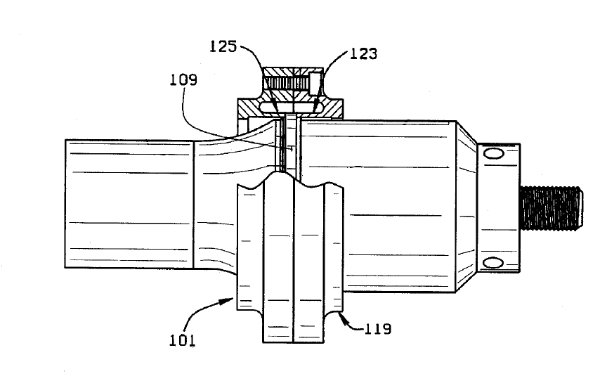
Cunningham 安装座
Cunningham[2] 专利 5590866(1997 年)。
|
|
|
波腹安装座
除 Elmore 安装座这一明显的例外,大多数波腹安装座依靠谐振板或圆盘(合称"梁")来实现解耦。它们能为横向载荷提供良好的支撑,但对轴向载荷的效果较差。
Elmore 安装座
Elmore[1] 专利 2891178(1959 年)。
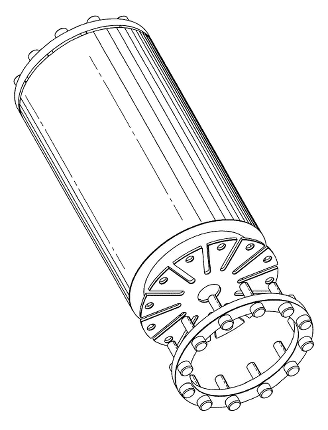
Polar 安装座
|
|
|
Isolation mounts
Overview
In most applications a means must be provided to mount the ultrasonic stack to a support structure. (Ultrasonic cleaning is one exception where the transducer is attached directly to the walls of the cleaning tank.) Depending on the application, the isolation mount may be attached to the transducer, booster (most common), and/or horn. The support structure could be some type of stand (e.g., for plastic welding) or a housing (e.g., for a hand-held device).
Requirements
- The mount must acoustically isolate the ultrasonic stack. Otherwise, ultrasonic energy will be transferred to the support structure.
— This energy is wasted (can't be applied to the load).
— This energy results in friction which may cause galling of the support structure, heating (e.g., if the housing will be hand–held), or noise. - The mount must allow reasonably precise positioning of the stack's output surface with respect to the load.
- The mount must prevent excessive axial or lateral deflection under the applied loads.
Types
Generally there are two types of mounts — elastomeric and rigid. Elastomeric mounts are those that employs an elastomer (e.g., rubber) for isolation. The most common elastomer shape is an O‑ring. Rigid mounts are those that use all-metal construction. These are used where high rigidity (low deflection under static load) and precise location are required. However, these are more expensive and less forgiving than elastomeric mounts.
O‑ring mounts
In addition to acoustically isolating the ultrasonic stack, O‑rings provide cushioning during impact loading. Typically, one O‑ring is mounted on each side of a O‑ring flange (figure 1). With approprite tolerances on the O‑ring flange and housing, the O‑rings are compressed slightly as the transducer body is assembled to the housing.
(In this discussion, "housing" is defined as those elements that capture the O‑rings. Thus, for instance, the housing could be rings around the O‑ring flange of a booster or the assembly that encloses a transducer body. In use, the housing is generally clamped in some manner to a support structure.)
|
|
|
|
||||||||||||||||
|
Notes for figure 1 —
- The inner housing ring (54) is pressed into the outer housing ring (56). This compresses the O‑rings against the O‑ring flange (46). Afterwards the antirotation pins (58) are installed.
- Once assembled, the housing can only be disassemblied by disintegrating the pins (e.g., by drilling or EDM). Hence, O‑ring replacement is not realistic.
|
|
|
|
||||||||||||||||||
|
Notes for figure 2 —
- The rear housing ring (66) is secured to the front housing ring (68) with screws (70), typically 6x. This compresses the O‑rings against the O‑ring flange (46).
- The clearance grooves in the housing rings into which the antirotation pins (58) nestle can be machined in the rings with a ball end mill before assembly. Then the antirotation pins must be installed before assembly. Alternately, the clearance grooves can be through-drilled after assembly and the antirotation pins can then be installed.
- This design allows easy O‑ring replacement but is more expensive to machine and assemble than that of figure 1.
Many variations are possible. For example, the inner ring of figure 1 could be a slip fit rather than a press fit. It could then be secured with a snap ring that seats into an inner groove in the outer ring. Groove-slot zzz.
O‑ring specifications
If the O‑ring is subject to compression or impact during the application (e.g., plastic welding) then a material with appropriate tensile strength must be chosen. For example, as a group polyurethane elastomers have high tensile strength whereas silicone elastomers have relatively low tensile strength (Parker (2), p. 2‑6). Coenen patent 4,647,336 suggests Viton fluorocarbon O‑rings with 90 durometer (p. 5, line 5). (Note — In many applications (e.g., plastic welding) only the rear O‑ring is compressed as pressure is applied to the horn's face. Then the front O‑ring can have a significantly lower durometer, if needed.)
After choosing the material, the O‑ring must be sized so that it can repeatedly absorb the loads; generally, higher loads require thicker O‑rings. For example, the transducer of figures 1 and 2 use O‑rings that are 3.5 mm thick. If a second resonator, such as a booster, helps to share the loads with the transducer then the transducer's O‑rings can be thinner.
After the O‑ring has been sized, the dimensions of the lands where the O‑rings seat in the front driver and housing can be adjusted to give the required fits. Generally, these dimensions can be the same as for static fluid sealing applications (Parker (2), section 4) except that the desired static O‑ring compression (below) must be observed. Of course, the O‑ring can be stretched to fit but this should be limited to 5% because the resulting internal stress causes more rapid aging (Parker (2), p. 3‑9).
Note — Square "O‑rings" have been tried. These tests indicated that square "O‑rings" were less effective in isolating the housing from the transducer body. The details of these tests are not known.
Static compression
After assembly the O‑rings must be sufficiently compressed that the housing doesn't "wobble" about the front driver. However, if the O‑rings are excessively compressed then they will transmit ultrasonic energy to the housing. The amount of compression will depend on the durometer of the O‑rings. Also, factors such as compression set, temperature effects, aging, etc. should be considered. (See (Parker (2).)
Coenen patent 4,647,336 suggests 10% compression (p. 5, line 31) when using Viton fluorocarbon O‑rings with 90 durometer (p. 5, line 5). (Coenen doesn't state if this compression is radial, axial, or both.)
For the 20 kHz transducer shown here (figures 1 and 2), the O‑rings are Parker 2‑230 or equivalent (nominal dimensions — 70.15 mm OD x 63.09 mm ID x 3.53 mm thick; Parker (2), p. 9-5). Each O‑ring has nominally zero radial clearance between it and the housing (i.e., a slip fit); this allows easier assembly. After assembly each O‑ring has 11% axial compression which, by Poisson's effect, also results in some radial compression.
Antirotation
Where a housing is required, the housing must be prevented from rotating with respect to the resonator. This maintains proper alignment of the ultrasonic stack with respect to the load (e.g., in plastic welding). In a transducer this also prevents the electrode wires from becoming twisted and possibly breaking. There are two common methods to accomplish this.
- Antirotation pins. See figures 1 and 2. The O‑ring flange is located in the vicinity of the node. It need not be located exactly at the node because the O‑rings can absorb some ultrasonic motion.
Solid pins and split pins have been used. However, under heavy loading where the housing is rigidly supported, the isolation O‑rings may compress excessively and the pins may then contact the clearance holes in the housing. If this occurs repeatedly (as with a plastic welder) and especially under impact, then the pins may fail by fatigue. In this case Spirol® pins are preferred for their superior impact resistance. Spirol® pins also allow looser drill tolerances and have other benefits. - Keyed designs. The resonator and housing may have keys (e.g., flats or splines) that mate with small clearances. These can allow for substantial axial movement between the housing and resonator while still tightly limiting rotation. For example, see the Coenen patent 4,647,336.
Grounding
In a transducer it may be desirable to have the transducer's body electrically grounded to the housing. If other grounding means are not convenient (e.g., because of assembly difficulties) then this ground path can be established by substituting a conductive O‑ring for one of the standard O‑rings. Such O‑rings are available for custom order from Parker Chomerics (3). If corrosion resistance is not important then try CHO‑SEAL 1285 (silver-plated-aluminum filled); otherwise, try CHO‑SEAL 6502 (nickel-aluminum filled). (Contact Parker or similar for specifics.)
Note that the base materials above are silicone which have relatively poor tensile strengths. Hence, if compressive/impact loads are expected then only a single conductive O‑ring should be used and it should be the front one (of the pair) so that its loading is minimal.
Rigid mount
Many rigid mount designs have been proposed. These attach precisely either at a node or antinode. In some cases there may be two attachment locations. For nodal attachment the mount must decouple the resonator's Poisson lateral motion. For antinodal attachment the mount must decouple the resonator's longitudinal motion.
The attachment member (which substitutes for the O‑ring) is generally tuned to the operating frequency; it may vibrate flexurally or, less often, longitudinally.
In the following, the mount is named either by its popularized name or by the inventor's name.
Nodal mounts
Nodal mounts are designed to decouple the resonator's lateral motion due to Poisson cross-coupling; they are not designed to decouple the resonator's longitudinal motion. Hence, these mounts must be positioned precisely at the resonator's node. Otherwise, some of the resonator's longitudinal motion will be imparted to the mount. This presents two difficulties.
- The node may not be suitable for mounting. For example, the transducer's node of figure zzz is located in the ceramics. For other resonators the node may be located in a radius. Although the resonator can be redesigned to reposition its node, this may cause problems for other design parameters such as gain.
- If a series of boosters of different gains are to be designed, then it may be desirable to locate each mounting ring at the same distance from the booster's input surface. (This is only required if the transducer-booster assembly must fit within certain fixed constraints of the support structure — e.g., in a plastic welding stand.) However, even if all boosters have identical dimensions in their back quarter wave section, the nodes will be in different locations depending on the booster's gain. This is because the node becomes a forward-facing "parabola" as material is removed in the front quarter wave section in order to increase the gain; the "parabolic" curvature increases as the gain increases. Hence, this may require some design contortions.
- In some cases the isolation mount is a separate part from the booter body. This reduces material and machining costs compared to a one-piece design. If the two parts are made of the same material then they can often be joined. For example, if both parts are titanium then they can be joined by electron beam welding. However, if the ring were titanium (for strength and to minimize deflection) and if the booster body were aluminum, then joining these dissimilar materials becomes a problem. Although the ring might be pinned to the booster body, the pin holes in the booster would eventually elongate due to impact or bending loads. Of course the booster body could be made of titanium but this might not be convenient for the overall system design (for example, if aluminum is preferred because of its better heat conduction).
Cunningham mount
Cunningham[2] patent 5590866 (1997).
|
|
|
Antinodal mounts
With the notable exception of the Elmore mount, most antinodal mounts rely on resonant plates or disks (together, "beams") for decoupling. These provide good support for transverse loads but are not as effective for axial loads.
Elmore mount
Elmore[1] patent 2891178 (1959).
Polar mount
|
|
|