螺纹与螺纹紧固件
目录
- 插图
- 图 1. 螺纹牙型对疲劳的影响
- 图 2. 螺纹加工
- 图 3. 螺纹加工方式对疲劳寿命的影响
- 图 4. 传统切削丝锥与冷成形丝锥
- 图 5. 晶粒结构 —— 冷成形螺纹与切削螺纹的对比
- 图 6. Spiralock 螺纹 —— 载荷分布
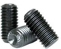
- 图 7. 内六角紧定螺钉,滚花端
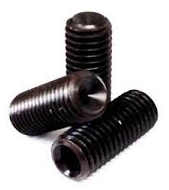
- 图 8. 内六角紧定螺钉,平端
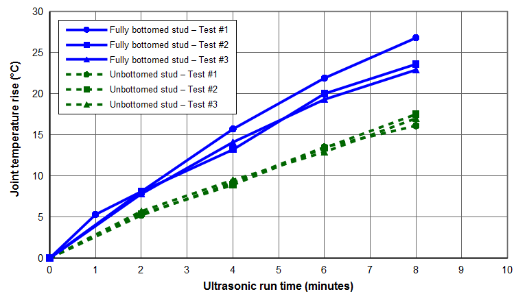
- 图 9. 螺柱底面接触对连接温度的影响
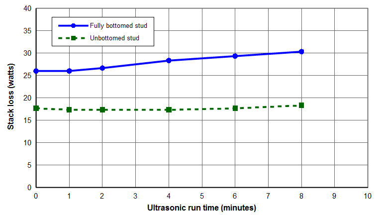
- 图 10. 螺柱底面接触对连接损耗的影响
- 图 13. 带 R 级螺纹的 3/8-24 整体式螺柱
- 图 14. 带 R 级螺纹的 1/2-20 整体式螺柱
- 图 11. 垫圈式螺柱(用于 20 kHz 的 1/2-20 螺纹)
- 图 12. 垫圈式螺柱图纸(用于 20 kHz 的 1/2-20 螺纹)
- 表格
- 表 1. 螺纹根部圆角半径(最小/最大)
- 表 2. 抵底螺柱 —— 扭矩
- 表 3. Loctite® 的扭矩性能
材料
螺栓和螺柱通常由高强度钢或钛制成。(偶尔也会使用不锈钢。)
超声换能器可以采用钛制中心螺栓或螺柱,以改善机电耦合。对于淬硬钢变幅杆,有人建议使用钛螺柱,以减少螺纹螺柱孔处的失效。
钛螺栓和螺柱的两个来源是 ——
螺纹
螺纹牙型
“标准”螺纹并未规定螺纹根部的圆角半径(尽管由于正常的加工操作会存在较小的圆角)。这些“尖锐”的根部会引起显著的应力集中,从而导致疲劳寿命降低(对于像热处理钢这样的缺口敏感材料尤为如此)。硬度越高 ==> 圆角半径越大。
为了提高疲劳寿命,螺柱和螺钉的外螺纹可以规定根部圆角半径。此类螺纹牙型规定为 UNR 或 UNJ。表 1 给出了这些螺纹允许的最小/最大圆角半径,并附有比对投影仪照片。
|
|
| 螺纹牙型 |
最小根部圆角半径 |
最大根部圆角半径 |
比对投影仪
照片 |
| 标准 |
无规定 |
无规定 |
 |
| UNR |
0.10825p |
0.14434p |
 |
| UNJ |
0.15011p |
0.18042p |
 |
|
表注 ——
- p = 螺距
- 最大根部圆角半径同时也是公称根部圆角半径(SPS Technologies[3],第 IV-8 页)。
- UNR 螺纹牙型的参考文献 —— Kanter[1],第 M-19 页
- UNJ 螺纹牙型的参考文献 —— 军用规范 MIL-S-8879C,第 27 页
- 比对投影仪照片引自 SPS Technologies[3],第 IV-9 页。
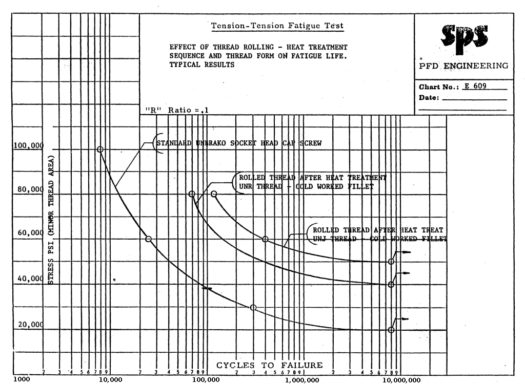
图 1 展示了螺纹牙型对疲劳的影响(Culp[0])。在 10e6 次循环的不再失效点(runout)处,UNR 螺纹牙型将持久极限应力从 20 ksi 提高到 40 ksi(+100%),而 UNJ 螺纹牙型将持久极限应力从 20 ksi 提高到 50 ksi(+150%)。
重要提示 —— 疲劳取决于许多因素,而这些疲劳曲线图未必详述了所有这些因素。因此,这些疲劳曲线图中的数据只能作为对比参考值,不应直接用于设计目的。
螺纹加工
外螺纹
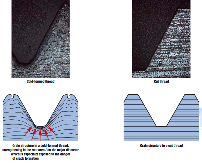
外螺纹通过模具间的滚压(适用于大批量生产,如标准内六角紧定螺钉)或切削(适用于小批量生产)加工而成。切削会去除材料并打断材料的自然晶粒流线。滚压则是使材料发生位移而不是将其去除,由于保留了自然晶粒流线,因此能获得更好的疲劳寿命。
滚压还通过在螺纹根部引入压应力来提高疲劳强度。然而,如果滚压之后进行热处理,这些压应力将会消失。因此,螺纹应在热处理之后进行滚压。其缺点是由于材料硬度的提高,滚压模具磨损得更快。
图 3 展示了热处理后进行滚压的优势。在 10e6 次循环的不再失效点处,热处理后再滚压将持久极限应力从 20 ksi 提高到 80 ksi(+300%)。
内螺纹
内螺纹用于容纳连接相邻谐振器的螺柱、端头以及换能器的叠堆螺栓。由于螺纹具有很高的应力集中,可能成为疲劳裂纹的起始部位。螺纹通常采用攻丝加工,不过特殊的螺纹牙型(例如带圆角根部)可能需要单点车削。
冷成形丝锥
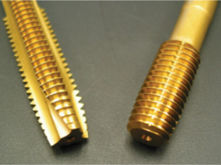
传统丝锥通过丝锥的切削作用去除材料。而冷成形丝锥具有楔形齿形,它使材料发生位移而不是去除材料。这种塑性冷作硬化在螺纹根部引入压应力,同时保持晶粒流线,并且还可能在螺纹根部留下圆角(图 5)。(不过请注意,如果零件在攻丝后进行热处理,这些压应力将被消除。)此外,螺纹表面光滑且经过挤压抛光(Destefani[1])。
这些优点能够提高疲劳寿命。抗静载能力也会提高。例如,Sağlam[1](第 214 页)报告称,对于旋合长度为 10 mm 的 M12x1.75 螺纹,平均最大拉伸载荷提高了 23%。
冷成形丝锥可用于较软的材料 —— 即抗拉强度不超过 1400 MPa 的材料(Emuge[1],第 19 页)—— 包括铝、Ti-6Al-4V 和某些钢材(Emuge[1],第 14 页)。
与传统攻丝相比,冷成形攻丝可以更快、刀具寿命也更长。此外,由于不产生切屑,排屑不成问题。然而,由于成形过程中摩擦很大,可能需要特殊的丝锥涂层和润滑剂(Emuge[1],第 4、24 页)。
|
|
图 5. 晶粒结构 —— 冷成形螺纹与切削螺纹的对比
(Emuge[1],第 18 页) |
|
非对称螺纹
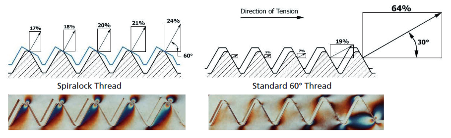
在传统螺纹中,前几圈螺纹承担了绝大部分载荷,其余螺纹贡献很小(图 6 右图)。采用诸如 Spiralock 这样的非对称螺纹可以使载荷分布得更加均匀。
|
|
| 图 6. Spiralock 螺纹 —— 载荷分布 |
|
螺柱
两个相邻的谐振器通过螺柱连接在一起。螺柱可以是独立的零件(本节讨论的内容),也可以与其中一个谐振器做成一体。
材料与尺寸
螺柱一般由高强度钢制成,有时也用钛。不锈钢螺柱也有使用。
常用尺寸为 1/2-20、3/8-24 和 M8。根据制造商的偏好,也可能使用其他尺寸。
安装
螺柱必须被固定在两个相邻谐振器之一中。否则,在拧紧或松开连接时螺柱可能会发生转动。此外,当超声激励时,还必须防止螺柱在螺纹孔内窜动。常用的方法有两种 —— 抵底螺柱和不抵底(浮动)螺柱。
抵底螺柱
抵底螺柱较为常用,因此首先介绍。然而,它可能存在发热和损耗问题,因此未必推荐使用。(参见关于螺纹锁固胶的讨论。)此外,它还可能在螺柱孔底部产生很高的静应力。这种静应力与超声应力叠加后,可能导致过早的疲劳失效,对于持久极限较低的铝变幅杆尤其如此。
抵底方法有两种 —— 完全抵底和楔紧。尚不清楚哪种方法更优。
完全抵底
在完全抵底方法中,螺纹孔用平底丝锥加工完成。然后将螺柱拧紧到孔的底面。螺柱可以带有滚花端,以防止其松动。(在图 7 中,请注意滚花位于锥体的外侧。此类螺钉可从 Unbrako 购得。)Branson Ultrasonics 使用这种方法。
楔紧
在楔紧方法中,螺纹孔用丝锥加工时在孔底留下数圈未加工完整的螺纹。当螺柱被拧入孔中时,其前端楔入这些未加工完整的螺纹中。Dukane 很可能采用这种方法。
扭矩
表 2 列出了几家超声公司推荐的扭矩。请注意,对于相同的螺柱尺寸,Branson 和 Dukane 推荐扭矩之间的差异很大。其中一些扭矩差异可归因于螺柱端部结构的不同以及抵底方式的不同。然而,扭矩差异如此之大,可能表明对扭矩要求存在某种根本性的误解。
|
| 螺柱尺寸 |
超声公司 |
推荐
扭矩 (Nm) |
| 1/2-20 |
Branson Ultrasonics
Patsonics |
51 |
| Dukane |
1.4 - 2.0 |
| Sonics & Materials |
61 |
| 3/8-24 |
Branson Ultrasonics
Patsonics |
33 |
| Dukane |
1.4 - 2.0 |
| M8-1.25 |
Branson Ultrasonics
Patsonics |
7.9 |
| Dukane |
1.4 - 2.0 |
| 1/2-20 至 3/8-24 阶梯螺柱
| Branson Ultrasonics
| 28
|
|
表注 ——
- 参考文献 ——
- Branson Ultrasonics[2](第 4 页)——"不遵守这些扭矩规范可能导致变幅杆/增幅杆螺柱松动、螺柱断裂以及无法解释的过载。" Branson 指出,曾在铝谐振器上使用过的螺柱,只要将滚花端上的铝屑清理干净即可重复使用。然而,曾在钛谐振器(推而广之,也包括钢谐振器)上使用过的螺柱不应重复使用,因为滚花已经受损,会使螺柱无法在孔底锁紧。
螺柱被抵入一个经平底丝锥加工的孔中。Culp[0]。
- Patsonics[1]
- Dukane[1](第 12 页)—— Dukane 的螺柱带有杯形端(cup point)。螺柱被楔入一个未经平底丝锥加工的孔中。
- Sonics & Materials[2](第 13 页)
除非另有说明,否则无论谐振器材料是铝、钛还是钢,变幅杆和增幅杆的螺柱扭矩均相同。
不抵底(浮动)螺柱
对于不抵底(浮动)螺柱,螺柱的端部不接触螺纹孔的底面(通常从孔底回退 1/2 圈)。由于螺柱不抵底,因此需要某种手段来防止它在螺纹孔内自由转动。
螺纹锁固胶
螺纹锁固胶涂敷在螺纹上,通常设计成在螺纹零件装配后厌氧固化。Loctite® 是一个著名品牌,不过还有许多其他品牌可供选择。
在不抵底螺柱上的应用
在不抵底螺柱上使用螺纹锁固胶时,推荐以下步骤 ——
- 彻底清洁螺柱和螺柱孔,去除所有油污和污染物。否则,螺纹锁固胶将无法正确粘附。(某些螺纹锁固胶对油污和污染物有一定的容忍度。请咨询制造商。)
- 将螺纹锁固胶涂敷到谐振器的螺纹上。
- 用手将螺柱拧到孔底,然后回退 1/2 圈。
- 在防止螺柱转动的同时,将防松螺母(jam nut)拧过外露的螺柱,直到螺母接触谐振器。将防松螺母牢牢拧紧。(注意 —— 防松螺母的端面必须与防松螺母的螺纹非常垂直。这将保证螺柱在螺纹锁固胶固化之前始终保持与谐振器的螺柱安装面垂直。如果没有加工合格的防松螺母,用板牙代替也能取得很好的效果。)
- 待螺纹锁固胶固化后,拆下防松螺母。
- 清除所有外露的未固化螺纹锁固胶。
尽管 Branson 使用带滚花端并抵底的螺柱,但它也可能(在适当的场合)将这种方法与 Loctite® 290 结合使用。一家生产超声金属焊机的公司使用不抵底螺柱配合 Loctite® 243(Culp[0])。
表 3 给出了这些 Loctite® 牌号的对比。
|
|
| Loctite® 牌号 |
破坏扭矩
(Nm) |
旋出扭矩
(Nm) |
松动扭矩
(Nm) |
| 243 |
20 |
7 |
24 |
| 290 |
10 |
29 |
30 |
|
表注 ——
- 上述扭矩适用于 M10 钢制螺母和螺栓。这些数值仅供对比之用。详见上面链接的数据手册。
- 破坏扭矩(Breakaway torque)—— 对于不抵底的紧固件,破坏螺纹锁固胶粘结所需的扭矩
- 旋出扭矩(Prevailing torque)—— 对于不抵底的紧固件,在螺纹锁固胶粘结被初步破坏后,继续转动紧固件所需的扭矩
- 松动扭矩(Breakloose torque)—— 对于抵底的紧固件,使其脱离抵底状态所需的扭矩
螺柱螺纹变形
可以以某种方式使螺柱螺纹变形,使其与相配的谐振器螺纹产生干涉。例如,可以在台虎钳或压力机中将螺纹牙顶压扁。螺柱螺纹的变形量应仅以足以防止螺柱在谐振器中自由活动为度;否则,在安装螺柱时谐振器的相配螺纹可能会被破坏。与使用螺纹锁固胶相比,这种方法不涉及任何附加材料、固化时间,也不存在螺纹锁固胶随时间推移而变质的可能。
抵底螺柱与不抵底(浮动)螺柱的对比
一般来说,螺柱不应在螺柱孔中抵底,因为这会在螺柱孔底部产生很高的静应力(对铝变幅杆来说尤其成问题),并且还会导致发热。Culp[0] 针对螺柱抵底的影响进行了测试。测试步骤如下 ——
- 将螺柱"非常紧"地(未规定具体扭矩)拧入螺纹孔底部。此后不再动该螺柱。
- 在换能器端面上涂一薄层 Molykote 润滑脂,并将变幅杆拧紧到换能器上。(每次测试都这样做,以减少受损连接污染测试结果的可能性。)
- 让该组件以全振幅运行八分钟,大约每两分钟测量一次温度。
- 让组件冷却到室温。
- 从换能器上拆下变幅杆。
- 重复步骤 2 至 5,共进行三次测试。
在完成上述针对抵底螺柱的测试后,将螺柱从螺纹孔底部回退 1/2 圈。然后针对不抵底螺柱重复上述步骤。
测试说明 ——
- 变幅杆是一根 40 kHz 高增益半波长无槽圆柱形铝变幅杆,直接连接到换能器上(无增幅杆)。
- 变幅杆的螺柱孔经平底丝锥加工,螺柱完全抵底。
- 螺柱为 M8 钢制,带滚花端。无论是否抵底,均使用 Loctite 242 牌号螺纹锁固胶将其固定在变幅杆中。
- 所有测试均使用同一根变幅杆和同一个换能器叠堆。
- 测试过程中叠堆未加冷却。
- 温度用热电偶测量,热电偶位于换能器的铝制前驱动块上、紧邻换能器-变幅杆连接处。
图 9 展示了完全抵底螺柱和不抵底螺柱各三次测试的结果。不抵底螺柱在温度方面的优势显而易见。此外,不抵底螺柱的数据离散度也更低。作为佐证,带不抵底螺柱的叠堆所测得的平均功率损耗比抵底螺柱低 37%。(注意 —— 不抵底螺柱使变幅杆的振幅降低了 6.3%。有限元分析预测的降幅为 5.2%。)
作为佐证,图 10 表明完全抵底螺柱的叠堆损耗明显高于不抵底螺柱。(每条曲线为相应三次测试的平均值。)此外,图 10 还表明不抵底螺柱的损耗在整个测试过程中相对稳定,而完全抵底螺柱的损耗则不断增大。
如前所述,抵底螺柱是完全抵底的(而非楔紧)。还应针对楔紧螺柱重复这些测试。
另请参见整体式螺柱和垫圈式螺柱。
垫圈式螺柱
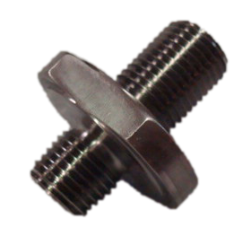
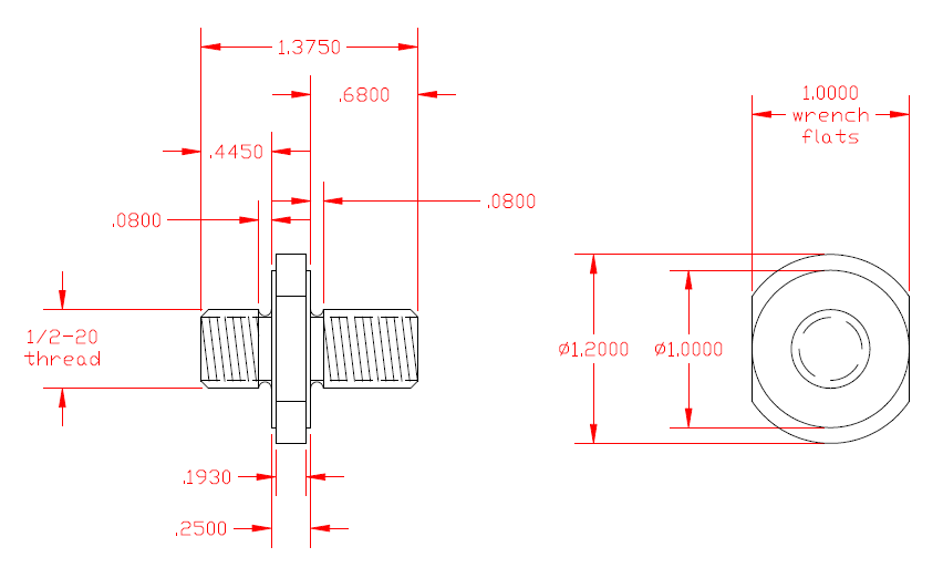
垫圈式螺柱用于替代常规螺柱。垫圈式螺柱由钛制成,通常用在增幅杆与变幅杆之间,或用在复合变幅杆中母杆与端头杆之间。
据报道,垫圈式螺柱在某些未具体说明的场合是有效的,原因可能是连接接触面积的减小,也可能是因为它们不在螺纹孔中抵底。由于垫圈部分具有相当的厚度,所连接的谐振器中至少有一个必须重新调谐以适应这一厚度。Branson Ultrasonics 曾使用过垫圈式螺柱。
|
|
图 11. 垫圈式螺柱(用于 20 kHz 的 1/2-20 螺纹)
(Culp[0]) |
|
|
|
图 12. 垫圈式螺柱图纸(用于 20 kHz 的 1/2-20 螺纹)
(Culp[0]) |
|
整体式螺柱
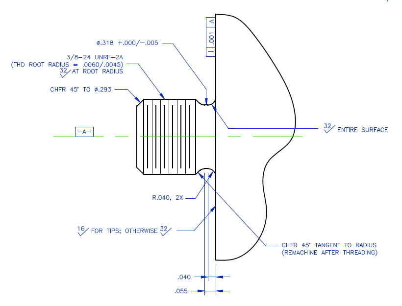
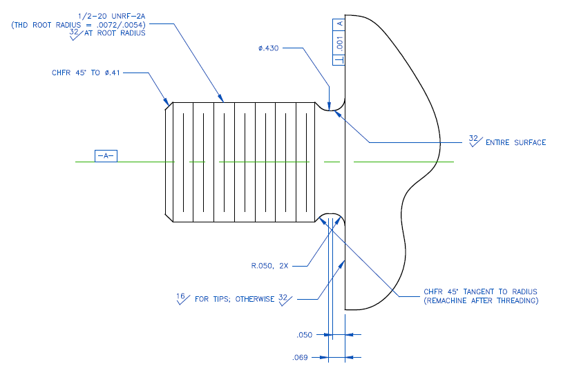
整体式螺柱作为谐振器的一体部分加工而成。它用于端头,也常用于小直径医用探头。它免去了对独立螺柱及相关装配的需要,保证了与相应连接面的最大垂直度,并将独立螺柱可能引起的摩擦损耗和应力降至最低。它还允许控制螺纹牙型 —— 例如,如有需要,可以规定采用具有较大根部圆角半径的 UNR 或 UNJ 螺纹。举例来说,这对于钢变幅杆可能是合适的,因为钢变幅杆的螺纹在热处理后可能对缺口敏感。
|
|
图 13. 带 R 级螺纹的 3/8-24 整体式螺柱
(Culp[0]) |
|
|
|
图 14. 带 R 级螺纹的 1/2-20 整体式螺柱
(Culp[0]) |
|
整体式螺柱最适合横向尺寸较小的谐振器。它们不适合横向尺寸较大的谐振器,因为为了加工出螺柱必须切除大量的材料。它们也可能不适合铝谐振器,因为铝螺纹材料的强度可能不足。
钢变幅杆的螺纹失效
已知钢变幅杆会在螺纹处发生失效。这很可能是由于热处理后的缺口敏感性所致。以下补救措施已被提出或尝试。
- 不要让螺柱抵底。抵底的螺柱会在螺纹上施加拉应力,从而降低疲劳寿命。
- 使用钛螺柱。钢变幅杆使用一段时间后,钢螺柱的螺纹侧面会出现微动磨损。由于钛的弹性模量约为钢的一半,它或许能够在超声应力下变形而不发生微动磨损。
- 提高变幅杆的增益。这将降低变幅杆的输入振幅,从而降低螺纹中的超声应力。
- 使用整体式螺柱。不再使用独立的螺柱,而是将螺柱作为变幅杆的一体部分加工出来。这样就可以严格控制螺纹牙型。
- 换用其他变幅杆材料。例如,如果需要耐磨性,可以尝试铝或钛变幅杆并加耐磨表面(如镀铬、D-gun 爆炸喷涂、碳化物)。然而,如果需要抗冲击性,那么像镀铬或 D-gun 这样相对较薄的涂层可能不合适。
对变幅杆应力和振幅的影响
螺纹嵌件(Helicoil 等)
Threads and threaded fasteners
Contents
- Figures
- Figure 1. Effect of thread form on fatigue
- Figure 2. Thread fabrication
- Figure 3. Effect of thread fabrication on fatigue life
- Figure 4. Conventional cutting tap and cold-forming tap
- Figure 5. Grain structure — cold-formed thread versus cut thread
- Figure 6. Spiralock threads — load distribution
- Figure 7. Socket set screw, knurled point
- Figure 8. Socket set screw, plain point
- Figure 9. Effect of stud bottom contact on joint temperture
- Figure 10. Effect of stud bottom contact on joint loss
- Figure 13. 3/8-24 integral stud with class R threads
- Figure 14. 1/2-20 integral stud with class R threads
- Figure 11. Washer stud (1/2-20 threads for 20 kHz)
- Figure 12. Washer stud drawing (1/2-20 threads for 20 kHz)
- Tables
- Table 1. Thread root radii (min/max)
- Table 2. Bottomed studs — torques
- Table 3. Loctite® torque performance
Materials
Bolts and studs are often made of high strength steel or titanium. (Stainless steel is occasionally used.)
Ultrasonic transducers may use a titanium center bolt or stud in order to improve electro-mechanical coupling. Titanium studs have been suggested for hardened steel horns in order to reduce failures in the threaded stud hole.
Two sources of titanium bolts and studs are —
Threads
Thread forms
"Standard" threads don't specify a radius at the root of the thread (although small radii will be present due to normal machining practice). These "sharp" roots cause significant stress concentrations which lead to reduced fatigue lives (especially in notch sensitive materials like heat treated steels). Higher hardness ==> larger radius.
In order to improve fatigue life, external threads for studs and screws can specify a root radius. The thread form is specified as UNR or UNJ. Table 1 shows the allowed min/max radii for these threads, together with comparator photographs.
| Table 1. Thread root radii (min/max) |
|
| Thread form |
Min. root radius |
Max. root radius |
Comparator
photograph |
| Standard |
No specification |
No specification |
|
| UNR |
0.10825p |
0.14434p |
|
| UNJ |
0.15011p |
0.18042p |
|
|
Table notes —
- p = thread pitch
- The max. root radius is also the nominal root radius (SPS Technologies[3], p. IV-8).
- Reference for UNR thread form — Kanter[1], p. M-19
- Reference for UNJ thread form — Military Specification MIL-S-8879C, p. 27
- Comparator photographs are from SPS Technologies[3], p. IV-9.
Figure 1 shows the effect on fatigue (Culp[0]). At the runout at 10e6 cycles, the UNR thread form increases the endurance stress from 20 ksi to 40 ksi (+100%) while the UNJ thread form increases the endurance stress from 20 ksi to 50 ksi (+150%).
|
|
| Figure 1. Effect of thread form on fatigue |
|
Important — Fatigue depends on many factors which are not necessarily detailed in these fatigue graphs. Therefore, the data in these fatigue graphs should only be considered as comparison values and should not be used for design purposes.
Thread fabrication
External threads
External threads are fabricated by rolling between dies (for large production lots such as standard socket set screws) or cutting (for small production lots). Cutting removes material and interrupts the natural grain flow. Rolling, which displaces material rather than removing it, gives better fatigue life because it preserves the natural grain flow.
Rolling also improves fatigue strength by inducing compressive stresses at the thread root. However, these compressive stresses are lost if the rolling is followed by heat treatment. Therefore, the threads should be rolled after heat treatment. The disadvantage is that the rolling dies wear more quickly because of the material's increased hardness.
Figure 3 shows the advantage of rolling after heat treatment. At the runout at 10e6 cycles, rolling after heat treatment increases the endurance stress from 20 ksi to 80 ksi (+300%).
Internal threads
Internal threads are needed to accommodate the studs that connect adjacent resonators, for tips, and for the transducer's stack bolt. Because of their high stress concentration, threads can be sites of fatigue crack initiation. Threads are typically fabricated by tapping although special thread forms (e.g., radiused root) may require single point turning.
Cold-forming taps
Conventional taps remove material by the cutting action of the tap. However, cold-forming taps have a wedging tooth profile that displaces material rather than removing material. This plastic cold working induces compressive stresses at the thread root while maintaining grain flow and also can leave a radius at the thread root (Figure 5). (Note, however, that the compressive stresses are removed if the part is heat treated after tapping.) Additionally, the thread surface is smooth and burnished (Destefani[1]).
These advantages improve fatigue life. Resistance to static stress also increases. For example, Sağlam[1] (p. 214) reports a 23% increase in average maximum tensile load for M12x1.75 threads with 10 mm of engagement.
Cold-forming taps can be used in softer materials — those with tensile strengths up to 1400 MPa (Emuge[1], p. 19) — including aluminum, Ti-6Al-4V, and some steels (Emuge[1], p. 14).
Compared to conventional tapping, cold-formed tapping can be faster with longer tool life. Also, chip removal isn't a problem because no chips are formed. However, because of the high friction involved in the forming process, special tap coatings and lubricants may be needed (Emuge[1], pp. 4, 24).
|
|
| Figure 4. Conventional cutting tap (left) and cold-forming tap (right) |
|
|
|
Figure 5. Grain structure — cold-formed thread versus cut thread
(Emuge[1], p. 18) |
|
Asymmetric threads
In conventional threads the first few threads absorb the majority of the load; the remaining threads contribute little (the right panel of Figure 6). The load can be more evenly distributed by using an asymmetric thread such as the Spiralock.
|
|
| Figure 6. Spiralock threads — load distribution |
|
Studs
Two adjacent resonators are joined together by a stud. The stud may be a separate entity (discussed here) or may be integral to one of the resonators.
Materials and sizes
Studs are generally made of high strength steel but sometimes of titanium. Stainless steel studs have also been used.
Common sizes are 1/2-20, 3/8-24, and M8. Other sizes may be used depending on a manufacturer's preferences.
Installation
The stud must be secured in one of the two adjacent resonators. Otherwise, the stud may rotate when the joint is either tightened or loosened. Also, the stud must be prevented from migrating within the threaded hole when ultrasonics are activated. Two methods are used — a bottomed stud or an unbottomed (floated) stud.
Bottomed stud
A bottomed stud is commonly used so it is described first. However, it may have problems with heating and loss and, therefore, may not be recommended. (See the discussion of threadlocking adhesives.) Additionally it may cause high static stress at the bottom of the stud hole. This static stress, when combined with the ultrasonic stress, may cause early fatigue failure, particularly for aluminum horns which have a low endurance limit.
There are two methods of bottoming — fully bottomed and wedged. It is not clear if either is superior.
Fully bottomed
In the fully bottomed method the hole is finished with a bottoming tap. Then the stud is torqued against the bottom of the hole. The stud may have a knurled end to prevent it from loosening. (In figure 7, note that the knurl is on the exterior of the cone. Such screws are available from Unbrako.) Branson Ultrasonics uses this method.
|
|
| Figure 7. Socket set screw, knurled point |
|
Wedged
In the wedged method the hole is finished with a tap that leaves several unfinished threads at the bottom of the hole. When the stud is torqued into the hole, its leading edge wedges into these unfinished threads. Dukane likely uses this method.
|
|
| Figure 8. Socket set screw, plain point |
|
Torques
Table 2 shows the recommended torques of several ultrasonic companies. Note the large differences in recommended torques between Branson and Dukane for the same stud size. Some of these torque differences may be attributed to the different end configurations of the studs and the method of bottoming. However, the torque differences are so large that they may indicate some fundamental misunderstanding of the torque requirements.
| Table 2. Bottomed studs — torques |
|
| Stud size |
Ultrasonic company |
Recommended
torque (Nm) |
| 1/2-20 |
Branson Ultrasonics
Patsonics |
51 |
| Dukane |
1.4 - 2.0 |
| Sonics & Materials |
61 |
| 3/8-24 |
Branson Ultrasonics
Patsonics |
33 |
| Dukane |
1.4 - 2.0 |
| M8-1.25 |
Branson Ultrasonics
Patsonics |
7.9 |
| Dukane |
1.4 - 2.0 |
| 1/2-20 to 3/8-24 step stud
| Branson Ultrasonics
| 28
|
|
Table notes —
- References —
- Branson Ultrasonics[2] (p. 4) —"Failure to follow these torque specifications
may result in the horn/booster stud loosening, stud breakage, and
unexplained overloads." Branson notes that a stud that has been used in an aluminum resonator can be reused if the aluminum bits are cleaned from the knurled end. However, a stud that has been used in a titanium resonator (and, presumably, a steel resonator) should not be reused because the knurls will have been damaged which will prevent the stud from locking in the bottom of the hole.
The stud is bottomed in a hole that has been bottom tapped. Culp[0].
- Patsonics[1]
- Dukane[1] (p. 12) — Dukane's studs have a cup point. The stud is wedged in a hole that has not been bottom tapped.
- Sonics & Materials[2] (p. 13)
Unless otherwise noted, the stud torque is the same for horns and boosters, regardless if the resonator material is aluminum, titanium, or steel.
Unbottomed (floated) stud
For an unbottomed (floated) stud, the end of the stud does not touch the bottom of the threaded hole (typically backed off 1/2 turn). Since the stud is unbottomed, some means is needed to prevent it from turning freely in the threaded hole.
Threadlocking adhesives
A threadlocking adhesive is applied to threads and is typically designed to cure anaerobically after the threaded parts have been assembled. Loctite® is one prominent brand although many others are available.
Application to an unbottomed stud
The following procedure is recommended when using a threadlocking adhesive with an unbottomed stud —
- Clean the stud and stud hole thoroughly to remove any oil and contaminates. Otherwise, the thread locking compound will not adhere properly. (Some threadlocking adhesives are somewhat tolerant of oil and contaminates. Consult the manufacturer.)
- Apply the threadlocking adhesive to the resonator threads.
- Hand bottom the stud in the hole and then back off 1/2 turn.
- While preventing the stud from rotating, run a jam nut over the exposed stud until the nut contacts the resonator. Securely tighten the jam nut. (Note — the faces of the jam nut must be very perpendicular to the jam nut's threads. This will assure that the stud remains perpendicular to the resonator's stud surface until the thread locking compound has cured. If a correctly machined jam nut is not available then a threading die works well.)
- After the threadlocking adhesive has cured, remove the jam nut.
- Remove any exposed uncured threadlocking adhesive.
Although Branson uses studs with knurled ends that are bottomed, it may also combine this with Loctite® 290 (where appropriate). A company that makes ultrasonic metal welders uses unbottomed studs with Loctite® 243 (Culp[0]).
Table 3 shows a comparison of these Loctite® grades.
| Table 3. Loctite® torque performance |
|
| Loctite® grade |
Breakaway torque
(Nm) |
Prevailing torque
(Nm) |
Breakloose torque
(Nm) |
| 243 |
20 |
7 |
24 |
| 290 |
10 |
29 |
30 |
|
Table notes —
- The torques are for M10 steel nuts and bolts. The values are for comparison purposes. See the above linked data sheets.
- Breakaway torque — for an unbottomed fastener, the torque required to break the threadlock bond
- Prevailing torque — for an unbottomed fastener, the torque required to continue to rotate the fastener after the threadlock bond has initially been broken
- Breakloose torque — for a bottomed fastener, the torque required to unbottom the fastener
Deformed stud thread
The stud thread can be deformed in some manner so that it interfers with the mating resonator thread. For example, the thread crests can be flattened in a vise or press. The deformation of the stud threads should only be enough to keep the stud from freely moving in the resonator; otherwise, the mating threads of the resonator may be destroyed as the stud is installed. Compared to using a threadlocking adhesive, this method doesn't involve any secondary material, cure time, or chance that the threadlocking adhesive might deteriorate over time.
Bottomed versus unbottomed (floated) studs
Generally, studs should not be bottomed in the stud hole because this causes high static stress at the bottom of the stud hole (particularly a problem for aluminum horns) and also causes heating. Culp[0] conducted tests on the effect of stud bottoming. The test procedure was —
- Tighten the stud "very tight" (no specified torque) into the bottom of the threaded hole. The stud was not disturbed thereafter.
- Apply a thin layer of Molykote grease to the transducer face and tighten the horn to the transducer. (This was done for each test to reduce the possibility that a corrupted joint might contaminate the results.)
- Run the assembly for eight minutes at full amplitude, taking temperature mesurements approximately every two minutes.
- Allow the assembly to cool to room temperature.
- Remove the horn from the transducer.
- Repeat steps 2 through 5 for a total of three tests.
After the above tests were completed for the bottomed stud, the stud was backed off 1/2 turn from the bottom of the threaded hole. The above procedure was then repeated for the unbottomed stud.
Test notes —
- The horn was a 40 kHz high gain half-wave unslotted cylindrical aluminum horn that was attached directly to a transducer (no booster).
- The horn's stud hole was bottom-tapped and the stud was fully bottomed.
- The stud was M8 steel with a knurled point. It was secured in the horn with Loctite grade 242 thread lock regardless of whether it was bottomed.
- The same horn and transducer stack were used for all tests.
- The stack wasn't cooled during the tests .
- The temperatures were measured with a thermocouple on the transducer's aluminum front driver just next to the transducer-horn joint.
Figure 9 shows the results for three tests each with fully bottomed and unbottomed studs. The temperature advantage of an unbottomed stud is clearly evident. In addition, the data scatter for the unbottomed stud is lower. For corroboration, the average measured power loss for the stack with the unbottomed stud was 37% lower than the bottomed stud. (Note — The unbottomed stud reduced the horn's amplitude by 6.3%. FEA predicts a reduction of 5.2%.)
As corroboration, figure 10 shows that the stack loss for the fully bottomed stud was significantly higher than for the unbottomed stud. (Each curve is the average of the three corresponding tests.) In addition, figure 10 shows that the loss for the unbottomed stud was relatively stable throughout the test whereas the loss for the fully bottomed stud increased.
As noted, the bottomed stud was fully bottomed (not wedged). The tests should be repeated for wedged studs.
|
|
| Figure 9. Effect of stud bottom contact on joint temperture |
|
|
|
| Figure 10. Effect of stud bottom contact on stack loss |
|
Also see Integral studs and Washer studs.
Washer studs
Washer studs replace conventional studs. Washer studs are made of titanium and are typically used between the booster and horn or in composite horns between the mother horn and tip horn.
These have been reported to be effective in certain unspecified situations, possibly due to the reduced joint contact area or because they don't bottom in the threaded hole. Because the washer section has appreciable thickness, at least one of the connected resonators must be tuned to accommodate this thickness. Washer studs have been used by Branson Ultrasonics.
|
|
Figure 11. Washer stud (1/2-20 threads for 20 kHz)
(Culp[0]) |
|
|
|
Figure 12. Washer stud drawing (1/2-20 threads for 20 kHz)
(Culp[0]) |
|
Integral studs
An integral stud is machined as an integral part of a resonator. It is used on tips and often used on small diameter medical probes. It eliminates the need for a separate stud and associated assembly, assures maximum perpendicularity to the associated joint, and minimizes frictional loss and stress that may be caused by a separate stud. It also allows control of the thread form — e.g., UNR or UNJ threads with larger root radii can be specified, if desired. This may be appropriate, for example, for steel horns where the threads may be notch sensitive after heat treatment.
|
|
Figure 13. 3/8-24 integral stud with class R threads
(Culp[0]) |
|
|
|
Figure 14. 1/2-20 integral stud with class R threads
(Culp[0]) |
|
Integral studs are most suitable for resonators with relatively small lateral dimensions. They are not suitable for resonators with large lateral dimensions since significant material must be machined away in order to create the stud. They also may not be suitable for aluminum resonators since the aluminum thread material may not be sufficiently strong.
Thread failures in steel horns
Steel horns are known to fail in the threads. This is likely due to the notch sensitivity after heat treatment. The following remedies have been suggested or tried.
- Don't bottom the stud. A bottomed stud places a tensile stress on the threads which reduces fatigue life.
- Use a titanium stud. After steel horns have been used for some time, the steel studs show fretting on the thread flanks. Since titanium has half the modulus of steel it may be able to deform under ultrasonic stress without fretting.
- Increase the horn's gain. This will reduce the horn's input amplitude, theregy reducing the ultrasonic stress in the threads.
- Use an integral stud. Rather than having a separate stud, the stud is machined as an integral part of the horn. Then the thread form can be closely controlled.
- Use a different horn material. For example, if wear resistance is needed then try an aluminum or titanium horn with a wear-surface (e.g., chrome, D-gun, carbide). However, if impact resistance is needed then a relatively thin coating like chrome or D-gun might not be suitable.
Effect on horn stress and amplitude
Thread inserts (Helicoil, etc.)