附录 A:陶瓷 33 与 31 工作模式的比较
用于大功率换能器的陶瓷通常分为两类。
- 33 型。对于 33 型,陶瓷的振动方向与电场方向平行。陶瓷通常为薄圆片,换能器使用多片陶瓷(一般至少一对,有时多达三对或四对,视功率承载要求而定)。这是最常见的类型。
- 31 型。对于 31 型,陶瓷的振动方向与电场方向垂直。通常使用单根管状陶瓷。该类型一般仅在特殊情况下使用。
33 模式 — 优点
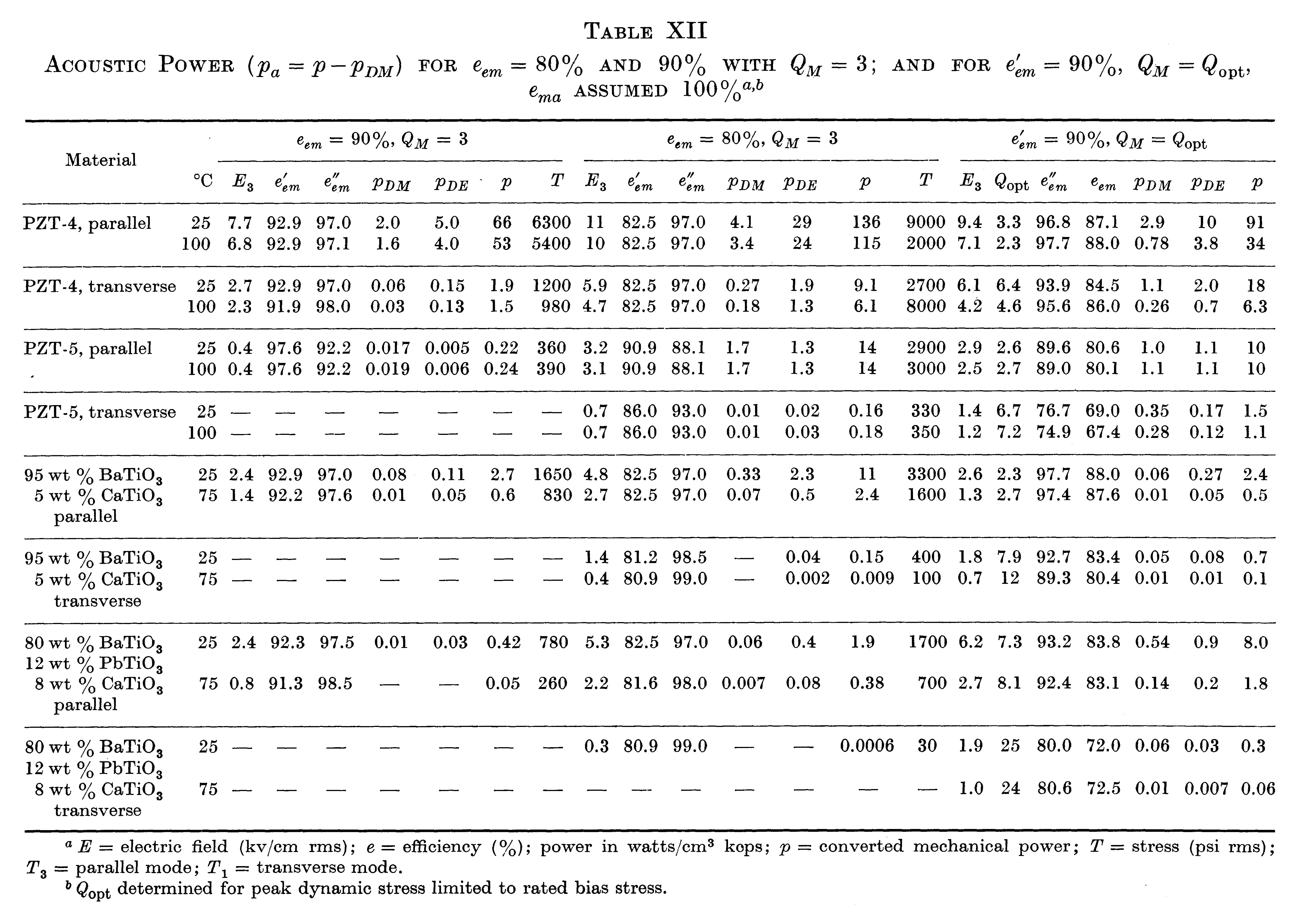
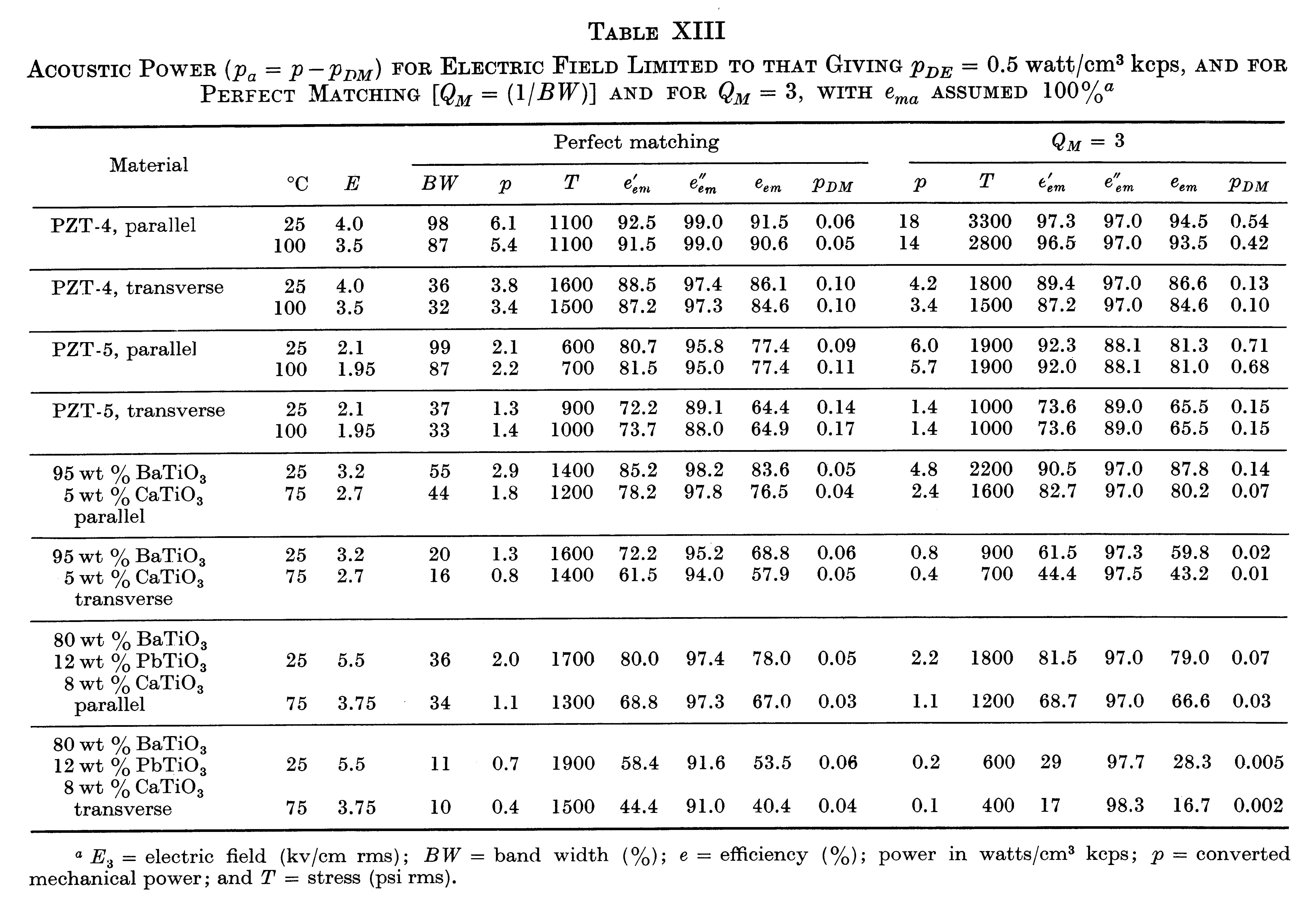
在匹配的 PZT4 平行模式换能器中,给定驱动电场下的应变和应力较小,但与匹配的 PZT4 横向模式换能器相比,带宽提高 2.6 倍,功率提高 1.7 倍。(Morgan Technical Publication TP-221,第 14 - 15 页)
"表 XII 和表 XIII 中的数据表明,在大功率换能器中采用平行模式而非横向模式具有若干优势。其中包括更高的带宽、相同功率下更高的效率(\( e'_{em} \)),以及给定 \( p_{DE} \)[电功率耗散]值下更高的功率。该模式下允许的偏置应力也更高。"(Berlincourt (3),第 253、255-256 页)请特别注意其中的 PZT-4 数据。
|
|
31 模式
以下是压电陶瓷以 31 模式工作的优缺点。这些未必都适用于某一具体设计或应用。
优点
- 由于设计涉及的零件可能更少(单件陶瓷加一或两个电极),制造成本可能更低。
- 一般而言,31 设计的陶瓷界面更少,因此此类界面带来的机械损耗更低。
缺点
- "与 33 型相比,……大约需要 5 倍的陶瓷才能维持相同的输出功率水平。"Channel Industries (1),第 6 页
- 电极化(内壁和外壁)的成本高于圆片(33 型)。
- 制造成本可能更高,因为长圆管的成品率可能低于圆片(33 型)。
- 对于外形尺寸相同的陶瓷叠堆,串联谐振(\( f_s \))与并联谐振(\( f_p \))之间的频率间隔可能更小。示例:管状陶瓷(0.650" 外径 x 0.300" 内径 x 1.000" 长)。
- 如果陶瓷管跨越波节,换能器可能难以在波节处安装。
zzz 此处插入表格
- 对于 31 模式,PZT4 的图 A1(b)(Berlincourt (3),图 16,第 216 页)表明,\( d_{31} \)
随静态压应力显著下降,而 \( d_{33} \) 实际上略有增大。因此,31 模式下所能承受的压缩预应力要低得多(Berlincourt (3),第 249 页)。这意味着受预应力限制的陶瓷动态应变可能低于期望值,因而输出振幅也可能低于期望值。
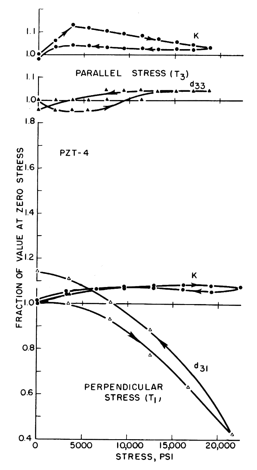
图 A1. 压应力的影响 -
(a) 33 方向(上方两图),(b) 31 方向(下方图) - PZT4 的图 A2(Morgan Technical Ceramics (4),第 6 页)表明,随着静态预载应力持续保持,\( d_{31} \) 随时间显著下降。相比之下,\( d_{33} \) 实际上略有增大。例如,在 1000 小时时,\( d_{31} \)
已下降约 29%,而 \( d_{33} \) 已增大约 12%。
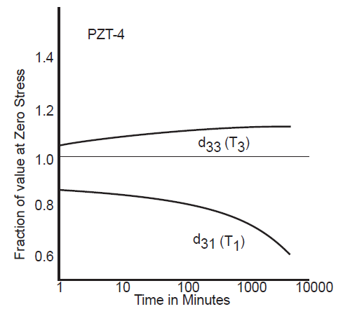
图 A2. \( d_{33} \) 和 \( d_{31} \) 在 10,000 psi[69 MPa]压应力下的老化
压应力平行(T3)和垂直(T1)于极化轴
建议
除特殊情况外,应采用 33 模式而非 31 模式。
Appendix A: Comparison of 33 and 31 ceramic operation
The ceramics that are used in power transducers typically fall into two categories.
- 33 type. For the 33 type the direction of ceramic vibration is parallel to the electric field. The ceramics are usually thin disks and the transducer uses multiple disks (generally at least one pair but sometimes as many as three or four pair, depending on the power handling requirements). This is the most common type.
- 31 type. For the 31 type the direction of ceramic vibration is perpendicular to the electric field. A single tube-shaped ceramic is typically used. This type is generally used only in special circumstances.
33 mode — Advantages
In a matched PZT4 parallel mode transducer, the strain and stress are less at a given driving electric field, but the bandwidth is up by a factor of 2.6 and the power by a factor of 1.7 compared to a matched PZT4 later mode transducer. (Morgan Technical Publication TP-221, pp. 14 - 15)
"The data in Tables XII and XIII show several advantages of the use of the parallel rather than the transverse mode in high power transducers. These include higher bandwidth, higher efficiency (\( e'_{em} \)) for the same power, and higher power for a given value of \( p_{DE} \) [electrical power dissipation]. Allowable bias stress is also higher in this mode." (Berlincourt (3), pp. 253, 255-256) Note particularly the PZT-4 data.
|
|
31 mode
The following are the advantages and disadvantages of using piezoelectric ceramics in the 31 mode. These may not all apply to a particular design or application.
Advantages
- Since the design may involve fewer parts (a single ceramic and one or two electrodes), the manufacturing costs may be less.
- Generally, a 31 design will have fewer ceramic interfaces so the mechanical loss from such interfaces is lower.
Disadvantages
- ".. approximately 5 times the ceramic is required to maintain the same output power level" compared to the 33 type. Channel Industries (1), p. 6
- The cost for electroding (inner and outer walls) is higher than for disks (33 type).
- The manufacturing cost may be higher because the yields for long cylinders may be lower than for disks (33 type).
- For a ceramic stack whose overall dimensions are identical, the frequency separation between series resonance (\( f_s \)) and parallel resonance (\( f_p \)) may be lower. Example: tube ceramic (0.650" OD x 0.300" ID x 1.000" long).
- The transducer may be difficult to mount at the node if ceramic tube spans the node.
zzz Insert table here
- For the 31 mode, figure A1(b) (Berlincourt (3), figure 16, p. 216) for PZT4 shows that there is a substantial decrease in \( d_{31} \)
with static compressive stress whereas \( d_{33} \) actually increases somewhat. Therefore, considerably lower compressive prestress can be tolerated in the 31 mode (Berlincourt (3), p. 249). This means that the dynamic ceramic strain, which is limited by the prestress, may be lower than desired and so the output amplitude may also be lower than desired.
Figure A1. Effect of compressive stress -
(a) 33 direction (top two graphs), (b) 31 direction (bottom graph) - Figure A2 (Morgan Technical Ceramics (4), p. 6) for PZT4 shows that there is a substantial decrease in \( d_{31} \) over time as the static preload stress is maintained. In contrast, \( d_{33} \) actually increases somewhat. For instance, at 1000 hours \( d_{31} \)
has decreased about 29% while \( d_{33} \) has increased about 12%.
Figure A2. Aging of \( d_{33} \) and \( d_{31} \) with 10,000 psi [69 MPa] compressive stress
parallel (T3) and perpendicular (T1) to the poling axis
Recommendation
Except in special circumstances, the 33 mode should be used instead of the 31 mode.